background image


Video Intercom Door Station 

(PD13A-S) 


User  Manual 

Summary of Contents for PD13A-S

Page 1: ...Video Intercom Door Station PD13A S User Manual...

Page 2: ...S INSPECTION OR OTHER INTERNET SECURITY RISKS HOWEVER OUR COMPANY WILL PROVIDE TIMELY TECHNICAL SUPPORT IF REQUIRED SURVEILLANCE LAWS VARY BY JURISDICTION PLEASE CHECK ALL RELEVANT LAWS IN YOUR JURISD...

Page 3: ...cate the receiving antenna Increase the separation between the equipment and receiver Connect the equipment into an outlet on a circuit different from that to which the receiver is connected Consult t...

Page 4: ...xempts de licence L exploitation est autoris e aux deux conditions suivantes 1 l appareil ne doit pas produire de brouillage et 2 l utilisateur de l appareil doit accepter tout brouillage radio lectri...

Page 5: ...l or dismantle the device When the product is installed on wall or ceiling the device shall be firmly fixed If smoke odors or noise rise from the device turn off the power at once and unplug the power...

Page 6: ...ct with the device cover because the acidic sweat of the fingers may erode the surface coating of the device cover Please use a soft and dry cloth when clean inside and outside surfaces of the device...

Page 7: ...ype I Door Station 12 5 2 Installation of Type II Door Station 14 5 2 1 Gang Box for Type II Door Station 14 5 2 2 Wall Mounting with Gang Box of Type II Door Station 14 5 3 Installation of Type III D...

Page 8: ...ing Main Sub Door Station 56 8 6 Batch Upgrading 59 8 6 1 Adding Devices for Upgrading 59 8 6 2 Upgrading Devices 61 9 Remote Operation via VMS A1 Client Software 63 9 1 System Configuration 63 9 2 De...

Page 9: ...s community villa and official buildings 1 2 Main Features Video intercom function HD video surveillance Max resolution 1280 720 30fps WDR 120 wide angle Self adaptive light supplement Access control...

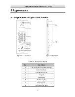
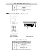
Page 10: ...nce of Type I Door Station Figure 2 1 Front View Figure 2 2 Side View Table 2 1 Descriptions of Keys No Description 1 Low Illumination Supplement Light 2 Built in Camera 3 LCD Display Screen 4 Keypad...

Page 11: ...r 11 Loudspeaker 12 TAMPER 2 2 Appearance of Type II Door Station 10 Figure 2 3 Front View Figure 2 4 Side View Table 2 2 Descriptions of Keys No Description 1 Low Illumination Supplement Light 2 Buil...

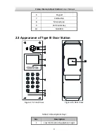
Page 12: ...anual 4 6 Keypad 7 Call Button 8 Microphone 9 Call Center Key 10 TAMPER 2 3 Appearance of Type III Door Station Figure 2 5 Front View Figure 2 6 Rear View Table 2 3 Descriptions Keys No Description 1...

Page 13: ...Video Intercom Door Station User Manual 5 No Description 2 Built in Camera 3 Loudspeaker 4 LCD Display Screen 5 Card Induction Area 6 Keypad 7 Call Button 8 Call Center Key 9 Microphone 10 TAMPER...

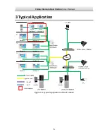
Page 14: ...Video Intercom Door Station User Manual 6 3 Typical Application Figure 3 1 Typical Application of Door Station...

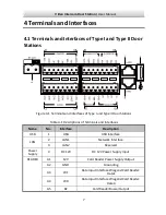
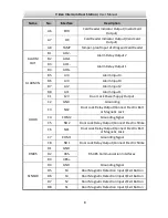
Page 15: ...ons Table 4 1 Descriptions of Terminals and Interfaces Name No Interface Description USB 1 USB USB Interface 2 LAN1 Network Interface LAN 3 LAN2 Reserved Power Supply 4 DC 12V DC 12V Power Supply Inpu...

Page 16: ...er Supply Output C2 GND Grounding C3 NC2 Door Lock Relay Output Connect Electric Bolt or Magnetic Lock C4 COM2 Grounding Signal C5 NO2 Door Lock Relay Output Connect Electric Strike C6 NC1 Door Lock R...

Page 17: ...face 2 LAN1 Network Interface LAN 3 LAN2 Reserved Power Supply 4 DC 12V DC 12V Power Supply Input A1 12V Card Reader Power Supply Output A2 GND Grounding A3 W1 Data Input Interface Wiegand Card Reader...

Page 18: ...Power Supply Output C2 GND Grounding C3 NC2 Door Lock Relay Output Connect Electric Bolt or Magnetic Lock C4 COM2 Grounding Signal C5 NO2 Door Lock Relay Output Connect Electric Strike C6 NC1 Door Lo...

Page 19: ...ease make sure your power supply matches your door station Make sure all the related equipment is power off during the installation Check the product specification for the installation environment 5 1...

Page 20: ...ole in the wall for inserting the gang box The size of the hole should be larger than that of the gang box The suggested size of hole is 404 5 length 123 5 width 48 depth mm 2 Insert the gang box into...

Page 21: ...13 Figure 5 4 Install the Door Station 5 Pull the door station downward and then push it towards the inside to make sure it fits the hole 6 Tighten the screws of the door station with the Allen wrench...

Page 22: ...for type II door station door station is 407 5 mm 135 mm 55 mm The dimensions above are for reference only The actual size can be slightly larger than the theoretical dimension 5 2 2 Wall Mounting wit...

Page 23: ...g Box into the Wall 3 Make sure the edges of the gang box align to the wall and the hook A and hook B of the gang box hook onto the wall 4 Route the cables of the door station through the cable hole 5...

Page 24: ...om Door Station User Manual 16 Figure 5 10 Install the Door Station 7 After fixing the door station onto the gang box secure it by inserting the plate and insert 2 POM2 screws Figure 5 11 Secure the D...

Page 25: ...th mm The dimensions above are for reference only The actual size can be slightly different from the theoretical dimension 5 3 2 Wall Mounting with Gang Box of Type III Door Station Steps 1 Chisel a h...

Page 26: ...ng Box into the Wall 3 Make sure the edges of the gang box align to the wall 4 Route the cables of the door station through the cable hole 5 Put the door station into the gang box Figure 5 14 Install...

Page 27: ...15 Tighten the Screws of Device 5 4 Wiring Description 5 4 1 Door Lock Wiring Figure 5 16 Door Lock Wiring Terminal NO1 COM1 is set as default for accessing magnetic lock electric bolt terminal NC1 C...

Page 28: ...netic Wiring Door Magnetic Wiring for Type I Type II Door Stations For type I type II door stations there are two optional ways of door magnetic wiring Figure 5 17 Door Magnetic Wiring for Type I Type...

Page 29: ...Type III Door Station To connect the door magnetic it is required to set the output of terminal AI2 to be door magnetic with Batch Configuration Tool or VMS A1 5 4 3 Exit Button Wiring Exit Button Wir...

Page 30: ...t of terminal AI1 to be exit button with Batch Configuration Tool or VMS A1 Figure 5 21 Exit Button Wiring for Type I Type II Door Stations 2 Exit Button Wiring for Type III Door Station Figure 5 22 E...

Page 31: ...please reboot the card reader after configuring the DIP switch The DIP switch description is shown in the following table No Description How to Configure 1 4 Set the RS 485 address ON 1 OFF 0 6 Select...

Page 32: ...ual 24 Wiegand Card Reader Wiring Figure 5 24 External Card Reader Wiring 5 4 5 Alarm Device Input Wiring Alarm Device Input Wiring for Type I Type II Door Stations Figure 5 25 Alarm Device Input Wiri...

Page 33: ...Wiring for Type III Door Station Figure 5 26 Alarm Device Input Wiring for Type III Door Station 5 4 6 Alarm Device Output Wiring Alarm Device Output Wiring for Type I Type II Door Stations Figure 5...

Page 34: ...Video Intercom Door Station User Manual 26 Alarm Device Output Wiring for Type III Door Station Figure 5 28 Alarm Device Output Wiring for Type III Door Station...

Page 35: ...on via Batch Configuration Tool and 9 Remote Operation via VMS A1 Client Software To activate the device locally refer to 7 1 Activating Device To configure the key parameters of device on the user in...

Page 36: ...strated in the table below The number key 2 The number key 8 The number key 4 The number key 6 Call Key When calling residents or center Confirm Return Delete 7 1 Activating Device Steps 1 Power on th...

Page 37: ...tion SIP server communication is not available Check if the SIP server IP address is correct SIP server rejected to login the device Check if the device No has been registered The network connection o...

Page 38: ...n the key and the key for 2s to enter the admin password interface 2 Enter the admin password and press the key Figure 7 3 Admin Password Interface The default admin password is 888999 Under the confi...

Page 39: ...ccomplishing local parameters settings In the main sub door station mode the serial No of main door station should be set as 0 and the serial No of sub door station should be larger than 0 For each ma...

Page 40: ...ursor to parameters to be configured 2 Press the key to enter or exit the editing mode 3 Press the key to exit the network configuration interface after accomplishing network parameters settings 7 3 3...

Page 41: ...he new password and confirm the new one 1 Move the cursor to parameters to be configured 2 Press the key to enter or exit the editing mode 3 Press the key to exit the network configuration interface a...

Page 42: ...the message Incorrect Main Card For the door station Door Phone Series if the amount of sub cards exceeds 2500 no more sub card can be issued and the station prompts the message No more sub card can...

Page 43: ...s Settings Interface 2 Set the volume 1 Move the cursor to parameters to be configured 2 Press the key to enter or exit the editing mode 3 Press the key to exit the volume settings interface 7 3 6 Abo...

Page 44: ...Unit No and the key and the Room No and the key 2 Press the key to start calling the resident 7 5 Unlocking Door Before you start Make sure your door station works as the main sub door station Purpose...

Page 45: ...Video Intercom Door Station User Manual 37 Swipe the card on the card induction area to unlock the door The main card does not support unlocking the door...

Page 46: ...motely Purpose You are required to activate the device first by setting a strong password for it before you can use the device Activation via Batch Configuration Tool and Activation via VMS A1 are sup...

Page 47: ...ic operation and remote operation of device cannot be performed You can hold the Ctrl or Shift key to select multiple devices in the online devices and click the Activate button to activate devices in...

Page 48: ...to be added has been activated Purpose For batch configuration tool software you should add device to the software so as to configure the device remotely The software provides 3 ways for adding the d...

Page 49: ...gged in will be added to the device list for configuration If you add devices in batch please make sure selected devices have the same user name and password 8 3 2 Adding by IP Address Purpose You can...

Page 50: ...n you add devices by IP Address IP Segment or Port No the devices should be online devices 8 3 3 Adding by IP Segment Purpose You can add many devices at once whose IP addresses are among the IP segme...

Page 51: ...or to enter the remote configuration interface Figure 8 11 Remote Configuration 8 4 1 System Click the System button on the remote configuration interface to display the device information Device Inf...

Page 52: ...ings interface Figure 8 14 Time Settings 2 Select Time Zone or Enable NTP Time Zone 1 Select a time zone from the drop down list menu 2 Click the Synchronization button NTP 1 Check the checkbox of Ena...

Page 53: ...ntenance 2 Click Reboot and the system reboot dialog box pops up Click Yes to reboot the system 3 Click Restore Default Settings to restore the default parameters 4 Click Restore All to restore all pa...

Page 54: ...le window pops up Select the saving path of remote configuration files and click Save to export the configuration file Figure 8 17 Export File 7 Click to select the upgrade file and click Upgrade to r...

Page 55: ...tivated status User Purpose You can edit the password for logging in the device Steps 1 Click the User button to enter the user information editing interface Figure 8 19 Select User Name 2 Select the...

Page 56: ...station Door Phone Series there are 5 choices for the working mode transparent channel elevator control card reader disable and custom 8 4 2 Video Intercom Click the Video Intercom button on the remo...

Page 57: ...ain door station Door Phone Series or Villa Door Station series at most 8 sub door stations can be customized Select doorphone as device type and the serial No is not necessary to configure Please uti...

Page 58: ...ator Step 1 Click the Access Control and Elevator button to enter password changing interface Figure 8 26 Access Control and Elevator Configuration 2 Set corresponding parameters on the access control...

Page 59: ...utput Configuration 2 Select I O input No input mode output No and output mode 3 Click the Save button to enable the settings For door station Door Phone Series there are 8 I O Input Terminals Termina...

Page 60: ...d volume output 3 Click the Save button to enable the settings 8 4 3 Network Local Network Configuration Steps 1 Click the Local Network Configuration button to enter local network configuration inter...

Page 61: ...door station type from the drop down list 4 Click the Save button to enable the settings After adding master station IP Address the linkage between indoor station and master station can be realized Af...

Page 62: ...cture and set the separator naming item and naming element 8 Click the Save button to enable the FTP parameters settings The default port No is 21 To enable anonymity or not is according to whether th...

Page 63: ...tore Default Settings button to restore all parameters excluding network parameters to the factory settings 8 5 Video Intercom Device Set up Tool Purpose You can assign the device to the community act...

Page 64: ...then assign devices to the community accordingly Figure 8 34 Setting a Community Structure 8 5 2 Setting Main Sub Door Station Setting Main Door Station Purpose You can activate the online main door s...

Page 65: ...network parameters for the main door station SIP IP address master station IP address center IP address center port No subnet mask and gateway address 5 Select an online door station enter the login p...

Page 66: ...b door station parameters sub door station amount floor No start IP address end IP address and then click the Calculate button to generate the sub door station end IP address and sub door station No l...

Page 67: ...device is successfully configured it prompts the note Configuring main door station parameters succeeded 8 6 Batch Upgrading In the device list area click to enter the batch upgrading interface Figur...

Page 68: ...User Manual 60 Figure 8 38 Login 2 Select a device enter the user name and password and click the Login Device button 3 Click the Add Device button and the device is added to the batch upgrading tool...

Page 69: ...IP address 3 Click the Add button Figure 8 40 Adding by IP Address IP Segment 8 6 2 Upgrading Devices There are 2 upgrading modes available upgrading by file and online upgrading Upgrading by File Upg...

Page 70: ...The batch upgrading tool will search the latest upgrading file for the device automatically You upgrade the device or devices via the local upgrade files Steps 1 Select a device or multiple devices an...

Page 71: ...eo intercom parameters accordingly Steps 1 Open the System Configuration page Path Control Panel Maintenance and Management System Configuration Video Intercom 2 Click the Video Intercom tab to enter...

Page 72: ...and master stations in total to the VMS A1 and add at most 16 door stations to the VMS A1 For video intercom devices you are required to create the password to activate them before they can be added...

Page 73: ...tab Video Intercom Device will display select Video Intercom Device and add indoor station and master station To add door station In the Server tab select Encoding Device Outdoor Device and add door...

Page 74: ...t the user name is admin Password Input the device password By default the password is 12345 7 Optionally you can check the checkbox Export to Group to create a group by the device name All the channe...

Page 75: ...box Then enter the user name and password for the devices to be added 9 2 2 Modifying Network Information Select the device from the online list click Modify Netinfo and then you can modify the netwo...

Page 76: ...cal engineer select Import File from Key Importing Mode drop down list and click to import the file 4 Input new password in text fields of Password and Confirm Password 5 Click OK to reset the passwor...

Page 77: ...nd Confirm Password 5 Click OK to reset the password STRONG PASSWORD RECOMMENDED We highly recommend you create a strong password of your own choosing Using a minimum of 8 characters including at leas...

Page 78: ...y available to door stations You are required to add storage server to the VMS A1 and format the HDDs first before uploading and storing captured pictures 9 4 1 Adding Storage Server Before you start...

Page 79: ...the captured picture storage Steps 1 Select the added storage server from the list and click Remote Config 2 Click Storage General to enter the HDD Formatting interface 3 Select the HDD from the list...

Page 80: ...lect the camera from the Camera Group list 3 Select the storage server from the Storage Server drop down list You can click Storage Server Management to add edit or delete the storage server 4 Check t...

Page 81: ...mple If you set the picture quota as 60 then the 60 of the storage space can be used for storing the captured pictures 6 Click Save to save the settings 9 5 Live View Steps 1 Enter the main view inter...

Page 82: ...tation User Manual 74 Figure 9 12 Live View of Doo Station Door Phone Series 2 Right click on the live view interface to display the menu and select Unlock to remote unlock the door Figure 9 13 Menu o...

Page 83: ...according to the real community situations and assign door stations and indoor stations to the community accordingly Refer 9 6 1 Group Management for detail steps You should manage groups first before...

Page 84: ...delete groups Three group types can be selected community outer door station and other Adding Group 1 Click the Group Management tab to enter the group management interface Figure 9 15 Adding Group 2...

Page 85: ...g Community Select Outer Door Station as group type and then input the outer door station No Range 1 to 9 to set the outer door station as shown in the figure below Figure 9 17 Adding Outer Door Stati...

Page 86: ...staff etc and you can assign cards to these staff and configure different permissions to them 3 Click OK to complete group adding Assigning IP Devices to Group After adding groups to Community Outer D...

Page 87: ...set a No for the door station 3 Click OK to save the settings Assigning Analog Devices to Group When assigning analog devices to group only analog indoor stations are supported 1 Click Add Analog to...

Page 88: ...vices in Batch Room Numbers here refers to the room numbers in each floor Adding Devices Singlly Enter the room No Figure 9 1 Adding Device Singly The room No format is like 101 2 Click OK to save the...

Page 89: ...the device modifying operation Deleting Device 1 Select an added device 2 Click Remove to pop up a dialog box Figure 9 22 Information 3 Click OK to complete the group deleting operation 9 6 2 Video In...

Page 90: ...door station to call the master station instead of VMS A1 Click Unlock to unlock the building or villa door via VMS A1 no matter whether answering the call from door station or not Click Answer to ans...

Page 91: ...door Station For each indoor station you can assign multiple cards and you can assign these cards to the door station in the same building Note Indoor extension does not support Card Management Before...

Page 92: ...card reader please swipe the card in the card reader and the corresponding card No will be shown automatically in the Card No textbox 3 Click OK to accomplish carding adding operation Click Delete Al...

Page 93: ...t Cards Steps 1 Select Community from the organization list like 1 1 1 and the indoor stations of the community will be listed in the resident list Figure 9 27 Clicking Card Selection 2 Click Card Sel...

Page 94: ...oxes of the cards or enter the card No in the filter textbox you need to assign to the indoor station and check the checkbox of door stations doorphones and outer door stations Only resident cards can...

Page 95: ...re 9 29 Displaying Card Issued After issuing resident cards to the indoor station the card No will also be listed in the resident list Issuing Other Cards Steps 1 Select Other from the group list like...

Page 96: ...ards are listed Figure 9 31 Selecting Cards 3 Check the checkboxes of the cards or enter the card No in the filter textbox you need to assign to the person and check the checkbox of door stations door...

Page 97: ...ill be reset to authorized ones Via VMS A1 there are two ways to cancel the cards which have been issued Option 1 Steps 1 Select Community from the organization list like 1 1 1 and the indoor stations...

Page 98: ...rface check the checkboxes of Room No for resident card or Name for other card click Cancel Card to cancel all card issued to the device Through Option 1 you can cancel card from single or certain doo...

Page 99: ...h Importing Unauthorized Cards Steps 1 Click Batch Import to enter the batch import interface as shown in the figure below Figure 9 36 Importing File 2 Click Export Template to export the template of...

Page 100: ...elect the saving file path and click Save 3 After batch exporting the unauthorized cards the excel will be generated in the saving directory 9 6 4 Notice Management Querying Call Logs Steps 1 Click Qu...

Page 101: ...king log querying page 2 Select the unlocking type device type and set the start time and end time and click Query Figure 9 38 Unlocking Log Interface 3 Click Export to export the unlocking logs as an...

Page 102: ...or Station User Manual 94 Figure 9 39 Tool Bar 2 Set the arming status of the device as armed and the alarm information will be auto uploaded to the client software when alarm occurs Figure 9 40 Devic...

Page 103: ...Video Intercom Door Station User Manual 95 Figure 9 41 Alarm Events After adding the device to the client software it will be armed automatically...

Page 104: ...etween two devices is recommended to be longer than 10 meters Here devices refer to indoor station outdoor station and master station Wiring Cables Cable Specification Power Cord of Door Station RVV 2...

Reviews: