Copyright 2004 M-B Companies, Inc.
All Rights Reserved
8
Setup and Adjustments
SETUP
Proper setup and leveling of your power broom will
increase the life of the brush and produces more
efficient movement of material. Visually inspect the
adjustments on the broom before each operating
session and measure the adjustments once every 10
hours.
The following procedures must be followed in the
prescribed order in order to be effective.
Once the broom has been properly adjusted, a short
operation period is recommended for break-in;
approximately 15 minutes. After this break-in period
repeat the leveling procedure to ensure that it is correct.
Mounting instructions can be found either in an
installation pamphlet or in the back of this manual.
LEVELING
•
After the broom is mounted to the tractor, loader,
mower, or skid-steer, park the unit on a flat level
surface; preferably concrete or asphalt.
•
If mounting to a skid-steer, lower the arms all the way
down and tilt the quick-attach all the way back.
•
If mounting to a loader, tilt the bucket cylinders all the
way back and lower the arms until the horizontal
mounting shaft is 18” from the ground. If there is a
way to set this location on the loader hydraulics, do
so at this time.
•
If mounting to a mower, set the down limit location so
that the horizontal mounting shaft is as close to 18”
as it can be. Because of the constrained spaces on
some mowers it maybe necessary that the shaft is
higher or lower.
•
*Note* - occasionally the horizontal mounting shaft is
replaced by pins or bolts based on mounting.
•
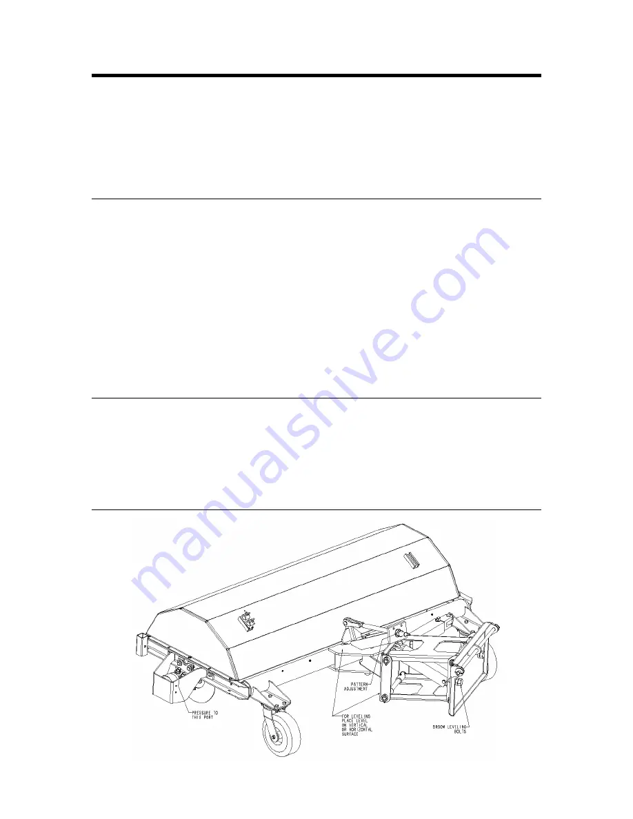
Swing the broom so that it is horizontal and tighten
the pattern adjustment nuts all the way down. (See
Illustration A)
•
Adjust the swing frame so that it are level by adjusting
the bolts in or out on the back of the swing frame.
(Refer to Illustration A) Adjust both bolts evenly to
maintain an even load on the mounting frame and the
arms. Check to see that the frame is level by placing
a small torpedo level vertically on the swing frame or
horizontally on the pivot frame.
•
Recheck for level after any other adjustments,
including pattern adjustment. If the broom is still level
continue to Pattern Adjustment. If not, re-start the
process of leveling.
PATTERN ADJUSTMENT
•
After the broom has been leveled, the last adjustment
is to set the brush pattern. This adjustment is located
at the top of the broom. (Refer to Illustration A)
•
With the unit set-up on a flat level surface adjust the
nuts on the top of the anchor so that the broom has
approximately 3” of contact from the front-most
contact point to the rear-most contact point.
Loosening the nuts will create more pattern.
•
Once this adjustment is set, it can be confirmed by
running the unit for about 30 seconds in the down
position while stationary. Stop the broom and back
the unit away. The ‘cleaned’ portion of the surface
should be 2”-4”.
ILLUSTRATION A


