background image

12 

6. Structure of the sections

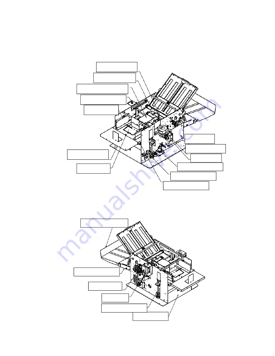
1) Layout Drawing of Overall Machine

Suction Belt Feeder Assy.

Air Adjustment Knob 

Paper Guide 

Double Feed Sensor 

Feed Angle Adj. Dial 

Table Up/Down Motor

Table Up/Down Drive 

Skew Adjustment Knob 

Paper Feed Table 

Auxiliary Feed Table 

Control PCB 

Separation Blower 

Suction Blower 

Drive Section 

Paper Ejection Table 

Aux. Paper Ejection Table

Door for Table 2

Table Up/Down Screw

Main Motor

Summary of Contents for 1800S

Page 1: ...Sales Service Repair Professional Service Fast Nationwide Shipping 1 866 455 9900 www OnlineSkyline com CustomerService onlineskyline com ...

Page 2: ...Ver 03 160939 NW MBM Corporation MBM Air Suction Folder Model 1800S SERVICE MANUAL ...

Page 3: ...Layout of Sensors Switch SW and Solenoids 15 6 5 Wiring Diagram 16 6 6 Suction Section 17 6 7 Paper Height Detection Section 17 6 8 Drive Section 18 6 9 Separating Air Section 18 6 10 Paper Transport Section 19 6 11 Paper Feed Table 19 6 12 Control Section 20 6 13 Option 20 7 Skew Adjustment 21 8 Disassembling Suction Belt Assembly Exchanging Suction Belt 23 9 Exchanging Clutch Unit 27 10 Exchangi...

Page 4: ...eplacing Other Sensors Paper Floating Height Sensor Top Cover Switch Paper Ejection Sensor and Others 33 17 Replacing Paper Ejection Belt and Replacing Ejection Roller Home Position Switch 34 18 Zero Setting of Folding Tables 1 and 2 35 19 Test Mode 36 20 Check Lamps Error Codes and Troubles 37 21 Troubleshooting 39 22 Error Codes 42 23 Other Troubleshooting and Cleaning 43 24 Other Adjustable Fun...

Page 5: ...nge odor Turn off the machine unplug it from the outlet and contact your dealer Do not operate the machine if the power cord is generating heat or emits a strange smell Turn off the machine unplug it from the outlet and contact your dealer If a foreign object enters into the machine turn off the power switch and unplug the power plug then consult your dealer In the event of a thunderstorm unplug t...

Page 6: ...5 WARNING 1 Moving Parts Warning Label WARNING HAZARDOUS MOVING PARTS KEEP FINGERS AND OTHER BODY PARTS AWAY ...

Page 7: ...6 WARNING 2 Moving Parts Warning Label WARNING HAZARDOUS MOVING PARTS KEEP FINGERS AND OTHER BODY PARTS AWAY ...

Page 8: ...y attention on over tension or over slack of wire harness to avoid touching to movable or rotary part 3 Clean the photo sensor to avoid the machine error 4 Clean the belts rollers and other related area to avoid paper feed error 5 When cleaning use a towel after wringing out water 6 Do not use an organic solvent to avoid machine trouble 7 After cleaning operate the machine only in the status that ...

Page 9: ...tection Sensor Auxiliary Paper Ejection Table Auxiliary Feed Table Power Switch Table 1 Paper Ejection Table Socket Operation Panel Air Adjustment Knob Paper Feed Table Weight Arm Door for Table 2 Top cover Knob Right side cover Table 2 L Stopper guide Table 2 is set under the Paper Feed Table in the machine which you find when opening the door for the table 2 ...

Page 10: ...9 Upper Cover is open to adjust belt feeder assembly Belt Feeder Assy Paper Floating Height Adjuster Suction Air Adjuster Error Code Chart Feed Angle Adjustment Dial ...

Page 11: ... inputting paper length Numerical key Use for inputting the number of sheets to be folded length of non standard size paper factors of interval function and others Table 2 stopper move mode key Use to adjust Table 2 Stopper position Table 1 stopper move mode key Use to adjust Table 1 Stopper position Paper length input mode key Use to input paper length for non standard norm paper Paper ejection r...

Page 12: ...e 2nd folded paper If fold type key is not pushed machine operates based on previously set folding pattern and speed 4 Fold by Adding Counter 4 1 Clear the numbers of counter and set it to zero 4 2 Press START key 4 3 Folding continues until out of paper in the Feed Table 5 Fold by Subtracting Counter 5 1 Set desired number of fold 5 2 Press START key 5 3 The folding stops at the time when reached...

Page 13: ... Knob Paper Guide Double Feed Sensor Feed Angle Adj Dial Table Up Down Motor Table Up Down Drive Skew Adjustment Knob Paper Feed Table Auxiliary Feed Table Control PCB Separation Blower Suction Blower Drive Section Paper Ejection Table Aux Paper Ejection Table Door for Table 2 Table Up Down Screw Main Motor ...

Page 14: ...13 2 Covers Paper Ejection Lower Cover Left Side Cover Rear Cover Door for Table 2 Table 1 Cover Top Cover Right Side Cover Front Cover Paper Ejection Upper Cover ...

Page 15: ...tor and Solenoid Separation Blower Table Up Down Motor Suction Section Solenoid Suction Blower Paper Ejection Belt Driving Motor Paper Ejection Roller Positioning Motor Table 1 Drive Motor Main Motor Table 2 Drive Motor ...

Page 16: ...talled for the area where inch size paper is not standard use Paper Empty Sensor Feed Sensor Double Feed Sensor Top Cover Interlock SW Paper Ejection Sensor Ejection Roller Home Position Sensor Main Motor Encoder Sensor Table 2 Hope Position Sensor Table 2 Encoder Sensor Paper Height Detection Sensor Table 1 Home Position Sensor Table 1 Encoder Sensor ...

Page 17: ...16 5 Wiring Diagram ...

Page 18: ...ust Valve Suction Blower Suction Belt Drive Shaft Feed Direction Adj Dial Feed Direction Adj Roller Suction Belt Coupling Feed Direction Adjust Roller Suction Belt Drive Roller Suction Chamber Suction Belt Paper Height Detecting Sensor Paper Floating Height Adjuster Paper Floating Height Adjuster ...

Page 19: ... Separation Air Section Clutch and Brake Timing Belt 270D x L Timing Belt 140 x L Timing Pulley Main Motor Separation Air Shutter Machine Front Stopper Wall Separator Rubber Separation Air Adjust Knob Separation Air Blower ...

Page 20: ...eed Roller A Feed Roller B Feed Roller C Feed Roller Feed Direction Adj Roller Suction Belt Drive Roller Feed Table Up Down Motor Feed Table Up Down Screw Skew Adjustment Knob L Stopper Guide Auxiliary Feed Table Paper Feed Table Paper Guide Paper Guide Fix Thumb Screw ...

Page 21: ...2 Scoring SRA3 W320xD450mm size is applicable for scoring 3 Large Capacity Stacker Can install Extension Conveyor for Ejection Table 4 Table 2 Interceptor Capable of Folding Longer A4 W210xD580mm or 680mm length paper can be folded into two 2 Power Switch Switching Power Supply Main Motor Main PCB ...

Page 22: ...nt Approx up to 129g m2 paper 1 Turn Feed Angle Adjustment Dial or depending on the status of skew Refer figures below and Pin Gauge Ex Single Fold Turn Direction Turn Direction Ex Double Parallel and All Others Turn Direction Turn Direction Paper Feed Direction Pin Gauge ...

Page 23: ...tes and Drawing of the following page Thereafter in case skew is not correctable by the Angle Adjustment Dial as above 7 1 adjustment by Skew Adjustment Knob is used i e whole Paper Feed Table is rotated Count degree of turn such as 1 4 turn of the Skew Adjustment Knob or Pin position to measure how much the Table is rotated Ex Single Fold Ex Double Parallel Fold or All Others Turn Counterclockwis...

Page 24: ...dge and Machine Front Paper Stopper Wall 8 Disassembling Suction Belt Assembly Exchanging Suction Belt 1 Remove firstly Table 1 and Paper Ejection Table Then remove Left rear and Right front Cover Side Covers Paper Leading Edge Screws are located inner side of machine 6 Fixing Screws Gap No Gap Machine Front Stopper Wall Feed Direction Feed Direction Skew Adjustment Knob at Feed Table Paper Feed T...

Page 25: ...ixing Screws Remove Screw Bracket for Cover 3 Fixing Screws Bracket of Cover is removed Remove Feed Angle Adj Unit Feed Angle Adj Unit is removed 2 Screws Remove Paper Floating Height Adjuster Paper Floating Height Adjuster is removed 2 Screws ...

Page 26: ...g angled direction Remove E Ring Pull out the Shaft per arrow direction Drive Roller and Drive Shaft are removed Replace Suction Belt Take note for direction of Belt Rotation by Arrow Mark Loosen Screws and remove Safety Cover Remove 2mm Hex Screw which are fixing Plastic Roller to the Shaft 2 screws By pulling the direction of arrow remove the shaft ...

Page 27: ...Keys 2 Set speed at lowest 1 3 Press Memory Key M1 and Main Motor starts to rotate 4 Press Memory Key M2 and Clutch is activated and Suction Belts starts to rotate 5 For some time period watch how these parts work No slippage of Suction Belt No meandering of the Suction Belt etc 6 To end Test Mode while pressing Clear Key press Test Key 組付け順番を確認してください 注意 クラッチシャフトを押しながら Take not for assembly sequen...

Page 28: ...Unit Assembly as supplied Remove screws of Coupling Loosen tension of Timing Belt by loosening 4 fixing screws Remove Clutch Unit Assembly From Clutch Unit Assy remove 1 Plate and 2 Collar They are not used for the machine Mount the new Clutch Unit Assy to the machine IMPORTANT While pressing shaft by Minus Driver fix Coupling by two 2 screws IMPORTANT Make sure positions of Fixing Screws are righ...

Page 29: ...tor Rubber and Suction Belt leaves approximately 0 5mm paper path gap Solenoid Unit as supplied Remove 2 Solenoid Fixing Screws Solenoid unit is removed Loosen M4 Nut and remove Plunger Assy After Solenoid Unit is exchanged to new manually move linkage per arrow mark and confirm that it moves smoothly Remove Front Stopper Wall by removing 3 screws IMPORTANT Both Two Separators must be replaced at ...

Page 30: ...rs procedure Loosen Timing Belt Tension by loosening 4 screws Remove Screws of Coupling Remove Clutch Unit Assembly Replace Timing Belt Belt tension must e controlled by giving 5mm distance when the belt is pushed Refer page 27 IMPORTANT While pressing shaft by Minus Driver fix Coupling by two 2 screws Remove Tension Roller Bracket 2 Screws Remove Screw of Idler Roller ...

Page 31: ...rew 2 screws Timing Belt is removed Open Door for Table 2 and open Belt Cover Replace with new Timing Belt and assemble in reverse procedure IMPORTANT Before giving tension to New Timing Belt i Make trapezoidal nuts right and left are in the same level ii Adjust in the same level for left and right height of nuts by rotating trapezoidal nuts The distance of arrow mark should be approx 8mm when bel...

Page 32: ...w and Springs are located in both sides Replace with a new Interceptor and mount in reverse procedure Remove Screws for Paper Guide 4 Screws in total 2 each on both sides Remove Connector for sensor Paper Guide is removed Turn Paper Guide upside down and replace Feed Sensor By removing Paper Guide Lower portion of Ultrasonic Sensor is visible Replace the Sensor By removing Sensor Cover on the Pape...

Page 33: ... is used in standard Remove Skew Adjustment Knob at Feed Table turning it counterclockwise Remove spring by using fine plier Remove screws for Paper Feed Table M3 Countersunk screw 4 pcs Remove Paper Guides on both sides from Paper Feed Table M3 Countersunk screw 4 pcs Remove Paper Guide Lock Screw Remove Cover of Up Down Lift unit M4 Screw 4 pcs Cut Cable Tie and remove Wiring Connector Replace P...

Page 34: ...Cover Switch Remove adjustment unit of Paper Floating Height Sensor 2 Screws Remove Cover 4 Screws Replace Paper Floating Height Sensor Remove Mounting Bracket of Top Cover 2 Screws Remove Top Cover Switch 2 Screws Remove Paper Ejection Upper Cover and Lower Cover Upper Cover Lower Cover Remove Sensor Cover 2 Screws Replace Paper Ejection Sensor ...

Page 35: ...ide Cover Switch Table 2 Set Switch Feed Table Lower Limit Switch Remove Paper Ejection Table from Machine Remove Cover from back side of the Table Remove Drive Pulley and Idle Pulley for Paper Ejection Belt Remove Belt as shown After replacing with new Belt assemble in revers procedure Replace Paper Ejection Home Position Switch ...

Page 36: ... compensation value of Table 1 press C Key and 1000 Key simultaneously for over 2 seconds 10 To lengthen 1T press Key To shorten 1T press Key 11 After compensation value is input press Store Key 2 Adjustment of Table 2 Lower Folding Table 1 Do the same preparation procedure of 1 1 thru 1 4 for Table 1 above 2 Press Fold Pattern Single Fold 3 Measure 2T length 2T length should be 1 2 of 420mm 210mm...

Page 37: ... 2 Stopper Position Adjust Key Move Table 2 Stopper Position Ejection Roller Position Adj Key Change Ejection Roller Position 1 thru 8 Paper Feed Table UP Down Key Paper Feed Table up or down Speed Selection Key Setting Speed 1 thru 5 Double Feed Sensor during Test Mode During Test Mode status of Ultrasonic Double Feed Sensor is indicated by Double Feed Key Lamp By putting two sheets between the S...

Page 38: ...5 Excessive loading of paper 2 If Check lamp 2 is flashing it may indicate 1 Improper setting of Table 1 2 Stopper lock at Table 1 3 If Check lamp 3 is flashing it may indicate 1 Electric plug of Table 2 is not inserted 2 Stopper lock of Table 2 4 If Check lamp 1 4 and 5 are flashing it may indicate 1 Double Feed Paper 5 If Check lamp 4 only is flashing it may indicate 1 Paper Jam ...

Page 39: ...d 7 If Check lamp 7 is lit it may indicate It lights after every 10 000 sheets of paper folded For reset turn on the machine while pressing Key You can disable this function when you turn on the machine while keep pushing Single Fold type key You can activate this function again when you turn on the machine with Gate Fold type key pushed Clean the Paper Transport Belt as frequently as needed depen...

Page 40: ... not move Connector Plug of Table 2 is pulled out Firmly plug in the connector Paper jam at inside Table 1 or 2 Remove paper jam by taking out Table 1 or 2 from machine Photo Sensor is dirty Clean photo sensor Motor is out of order for Table 1 or 2 Replace motor of Table 1 or 2 Control PCB is out of order Replace Control PCB Frequently Paper Ejection jams Position of Ejection Roller is not set sui...

Page 41: ...Paper Feed Roller Warn out Paper Feed Belt Replace Paper Feed Belt Out of specification paper is used Use paper within machine specification Dirt or Dirty Separator Clean Separator Separator position is too high Set Gap between Separator and Paper Feed Belt at 0 5mm Use feeler gauge Frequently double feed of sheet occur Separator is worn out Replace Two 2 Separator at the same time Dirty Separator...

Page 42: ...cur Paper Feed Table is not square against Machine Front Stopper Wall Make Paper Feed Table square by Skew Adjustment Knob at Paper Feed Table Sheet is not cut square Make Paper Side Edge square against Machine Front Stopper Wall by Skew Adjustment Knob at Paper Feed Table Or use squarely cut paper Torn paper chip stays in paper path Clear out paper chip from paper path Dirty Paper Folding Roller ...

Page 43: ...per size use Paper Length Manual Input Mode E 13 Double Feed Error Remove Double Fed Paper from Ejection Table E 51 The door of the Table 2 is open or Top Cover is open E 52 Paper left in Paper Feed Sensor area or Paper Feed Sensor is dirty E 53 Failure of Paper Height Sensor E 54 Failure of Feed Table Up and Down Motor E 55 Failure of Main Motor or the Encoder is dirty E 56 Paper Ejection Roller ...

Page 44: ...43 23 Other Troubleshooting and Cleaning Refer Operation manual page 47 and on for Cleaning Paper Jam Cleaning Sensors Cleaning Fold Roller Paper Feed Belt and Cleaning Suction Belt ...

Page 45: ...emovable by hand 2 Adjustment of Base Plate of Table 2 Position of Base Plate of Table 2 is adjustable back and forth As factory default setting it is placed at 3rd hole medium position General Guidance Thicker Paper In case frequent slippage of paper is observed remove Base Plate Fixing Screws located both sides of Table 2 Place the Base Plate for Thicker side of location and fix the Screws Thinn...

Page 46: ...eed Table Thicker Paper In case higher folding pressure is desired remove Thumb Screw and pull the Bracket so that Folding Roller Spring gives higher pressure to the Roller Left and Right Setting should be the same strength Thicker Paper Higher Pressure Thinner Paper In case paper is wrinkled remove Thumb Screw and push the Bracket so that Folding Roller Spring gives lower pressure to the Roller L...

Page 47: ...46 ...

Reviews: