


12
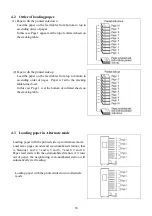
3.1.3 Stacking table assembly
(1) Insert the 2 stacking side guides and the stacking end
guide in the stacking table, making sure not to set
them in the wrong direction.
(2) Insert the 2 stacking poles in the holes and fix them
while sliding them along the slot.
(3) After having inserted a stacking side guide, please
attach a guide fix screw.
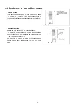
3.1.4 Stacking table
(1) Fit the tumbler-shaped hooks on the stacking table into
the hooks of the front foot rubber base (two places)
while fitting the tip notch of the stacking table to the
collator’s
s
hift
roller, then tilt the stacker table on either
right or left side (right with the roller on the right, left
when on the left), and insert the stacking table hooks in
the opening on the front foot rubber base. Make sure
the hooks are firmly fitted on both right and left sides.
Caution!
If the depressed portion on the stacking table is not
properly set in the s
hift
roller, “LOCK” will be
indicated on the Counter display when the CHECK key
or START key is pressed. If the machine is continuously
operated in this way, it may cause a breakdown of the
s
hift
motor. In such a case, turn off the power,, and
after the stacking table is removed from the machine,
start the machine again to perform normal operation
and confirm that the s
hift
roller moves from side to side
and
“
LOCK
”
is not shown on the display. Then, reset
the machine properly in accordance with the
instructions specified in the Operation Manual.
(If the s
hift
roller moves from side to side even after the
stacking table is removed, contact your dealer.)
If the
CRISS-CROSS /5
key is pressed for three seconds after
the MODE key is pressed, the
s
hift
roller will perform one
operation.
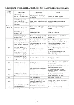
(2) Install the aligning wire.
[1]After installing the stacking table in the collator,
insert the rear part of the aligning wire into the wire
insertion hole in the collator.
[2]Pinch the bent part at the aligning wire tip with your
fingers and draw it to the front. Then, fit it on the
wire insertion hole in the stacking table.
[3]While pinching the wire as it is, insert the bent part
at the wire tip into the wire insertion hole in the
stacking table.
Shift roller
Guide fix screw
(L/R)
Summary of Contents for FC 10 PLUS
Page 1: ... 0 SERVICE MANUAL MBM TABLETOP COLLATOR MODEL FC 10 PLUS R e v 1 0 㻌 㻌 㻌 㻌 Sep 09 2016 ...
Page 7: ...6 䐟㻌 䐠㻌 䐡 䐢 䐣 䐤 䐥 䐦 䐧 䐨 䐩 䐪 䐫 䐯 䐰 䞣 䞢 䞡 䐲 䐱 䞧 䞦 䞥 䞤 䞨 䐬 䐭 䐮 䞪 䞩 䞫 1 2 Operation Panel ...
Page 20: ...19 ...
Page 21: ...20 6 MAIN PRINTED CIRCUIT BOARD ...
Page 22: ...21 7 Wiring Diagram ...
Page 33: ...32 Dismount the clutch holder Dismount the paper feed clutch ...
Page 35: ...34 Lift up the flat idler pulley and slip off the timing belt ...


