22
8.
Paper detection
wire angle adjustment procedures
(1)
Dismount the cover on the operating side
(2)
Unscrew the screws on the sheet metal frame and open it
(3)
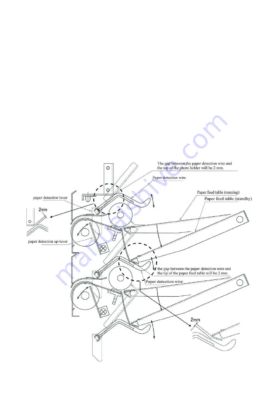
Lowering the paper feed table, loose the Philips screws of the paper detection up-lever, and move
to the right and left sides to make it free
(4)
When the paper detection up-lever is moved to the right side, the paper inspection wire will move
to the upper side by the paper detection lever.
(5)
(a) Adjustment procedures of station 1
Adjust the position of the paper detection paper up-lever, and fasten it with a Philips screw in order
that the gap between the paper detection wire and the top of the photo holder will be 2 mm.
(b) Adjustment procedures of stations 2 to 10
Adjust the position of the paper detection paper up-lever, and fasten it with a Philips screw in order
that the gap between the paper detection wire and the tip of the paper feed table will be 2 mm.
(6)
Close the operating panel opened in (2) and fix with screws.
(7)
Mount the cover at the operating side for the completion.
Summary of Contents for FC 10 PLUS
Page 1: ... 0 SERVICE MANUAL MBM TABLETOP COLLATOR MODEL FC 10 PLUS R e v 1 0 㻌 㻌 㻌 㻌 Sep 09 2016 ...
Page 7: ...6 䐟㻌 䐠㻌 䐡 䐢 䐣 䐤 䐥 䐦 䐧 䐨 䐩 䐪 䐫 䐯 䐰 䞣 䞢 䞡 䐲 䐱 䞧 䞦 䞥 䞤 䞨 䐬 䐭 䐮 䞪 䞩 䞫 1 2 Operation Panel ...
Page 20: ...19 ...
Page 21: ...20 6 MAIN PRINTED CIRCUIT BOARD ...
Page 22: ...21 7 Wiring Diagram ...
Page 33: ...32 Dismount the clutch holder Dismount the paper feed clutch ...
Page 35: ...34 Lift up the flat idler pulley and slip off the timing belt ...


