


23
9. How to replacement of Parts
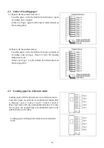
9.1
Operation panel side
Remove the decorative cover on the operation panel side.
Unscrew total 10 of screws at the right and left
sides of the cover.
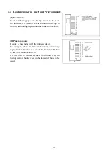
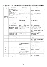
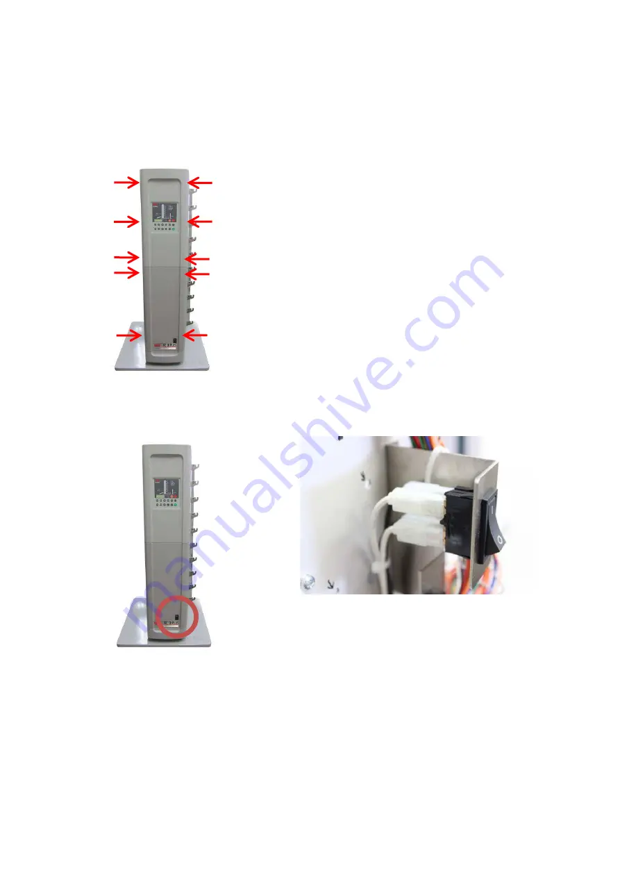
9.1.1 Power switch
Note: There are 4 wires to the power switch, and
the 2 front side wires of them are white and the 2
back side wires are black.
Be careful not to make mistakes.
Summary of Contents for FC 10 PLUS
Page 1: ... 0 SERVICE MANUAL MBM TABLETOP COLLATOR MODEL FC 10 PLUS R e v 1 0 㻌 㻌 㻌 㻌 Sep 09 2016 ...
Page 7: ...6 䐟㻌 䐠㻌 䐡 䐢 䐣 䐤 䐥 䐦 䐧 䐨 䐩 䐪 䐫 䐯 䐰 䞣 䞢 䞡 䐲 䐱 䞧 䞦 䞥 䞤 䞨 䐬 䐭 䐮 䞪 䞩 䞫 1 2 Operation Panel ...
Page 20: ...19 ...
Page 21: ...20 6 MAIN PRINTED CIRCUIT BOARD ...
Page 22: ...21 7 Wiring Diagram ...
Page 33: ...32 Dismount the clutch holder Dismount the paper feed clutch ...
Page 35: ...34 Lift up the flat idler pulley and slip off the timing belt ...


