


58
11.4 Check on sensor function
Lamp
Function
Remarks
Station 1 to 10
(Green lamp)
Status of paper switch at each
station
The lamp of the station where paper is loaded lights.
Station 1 to 10
(Red lamp)
Status of paper feed photo
sensor at each station
The lamp of the station where paper jam occurs lights.
DOOR lamp
State of the back door
It lights when the back door is open.
JAM lamp
Status of paper ejection photo
sensor
It lights when paper ejection photo-sensor is shut.
Status of paper ejection
direction
It lights when the ejection direction is set to the left.
ERROR (L) lamp
Status of the left side equipment
It lights when there is an error in the left side
equipment.
ERROR (R) lamp
Status of the right side collator
It lights when there is an error in the right side
equipment.
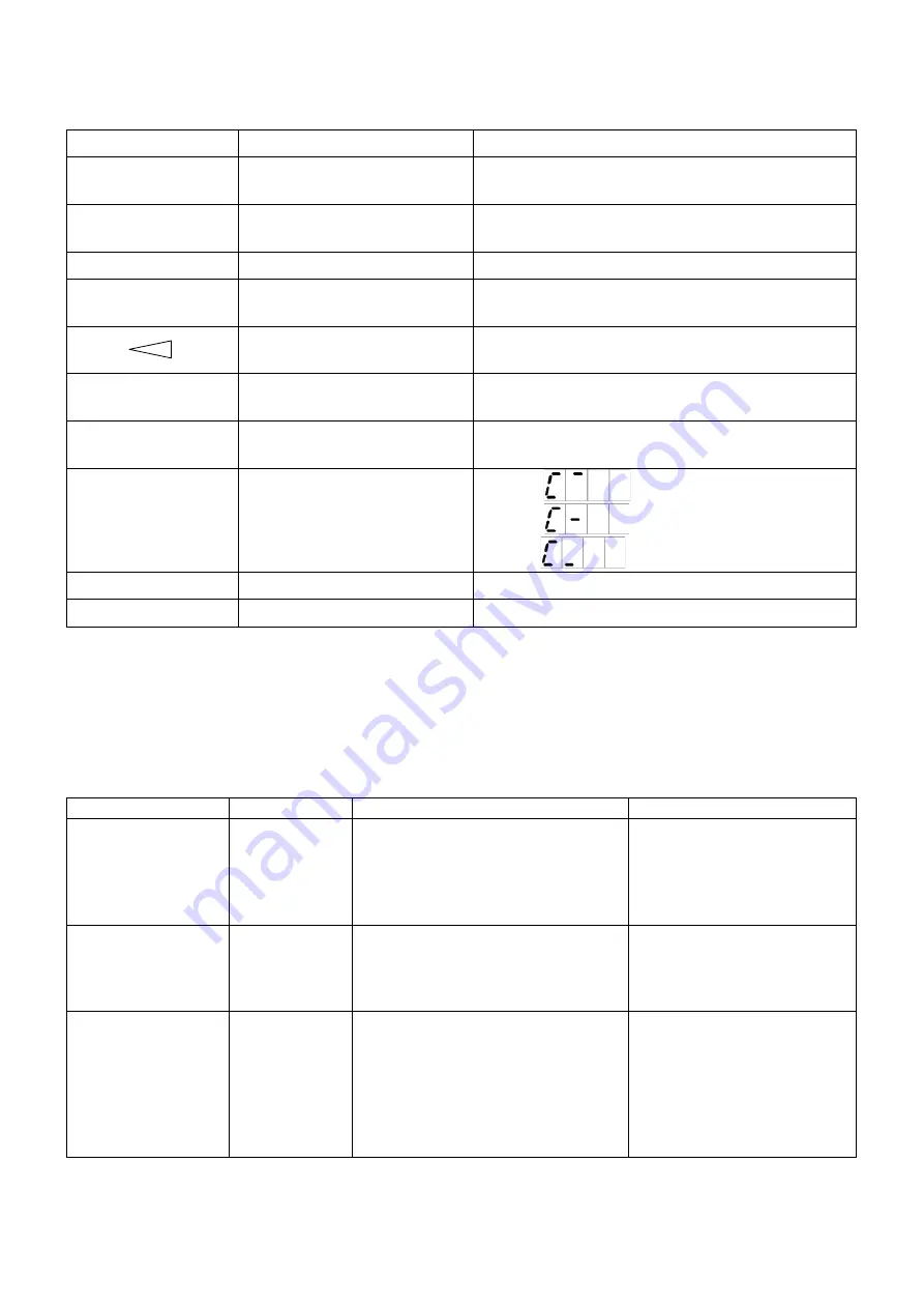
COUNTER
Status of the paper feed table
(third digits)
It shows
when it is at the upper limit.
It shows
when it is at the lower limit.
It shows
while it is halfway.
SPEED lamp
Display of collation speed
It lights when high-speed collation is set.
SHIFT lamp
Shift origin switch
It lights when the switch is set at stacker starting point.
11.5 Photo sensor check mode
While the photo sensor check mode is set, the status of the paper feed photo-sensor can be checked in
details with the data displayed on the counter.
࣭
Counter display
Counter
Display
What is meant
Remarks
Number in the fourth
digit
Number of
station
1
–
9: Paper feed photo for Stations 1
to 9
A: Paper feed photo for Station 10
b: Full stacking photo
Number in the third
digit
“
0
”
-
Always
“
0
”
Number in the
second and first
digits
Photo-sensor
output value
(Shading) 00
–
FF (Penetration)
[ Reference value ]
Penetration : over F0
PPC 64gsm: d3
PPC 157gsm: CE
*The performance will become
different among machines.
Summary of Contents for FC 10 PLUS
Page 1: ... 0 SERVICE MANUAL MBM TABLETOP COLLATOR MODEL FC 10 PLUS R e v 1 0 㻌 㻌 㻌 㻌 Sep 09 2016 ...
Page 7: ...6 䐟㻌 䐠㻌 䐡 䐢 䐣 䐤 䐥 䐦 䐧 䐨 䐩 䐪 䐫 䐯 䐰 䞣 䞢 䞡 䐲 䐱 䞧 䞦 䞥 䞤 䞨 䐬 䐭 䐮 䞪 䞩 䞫 1 2 Operation Panel ...
Page 20: ...19 ...
Page 21: ...20 6 MAIN PRINTED CIRCUIT BOARD ...
Page 22: ...21 7 Wiring Diagram ...
Page 33: ...32 Dismount the clutch holder Dismount the paper feed clutch ...
Page 35: ...34 Lift up the flat idler pulley and slip off the timing belt ...


