65
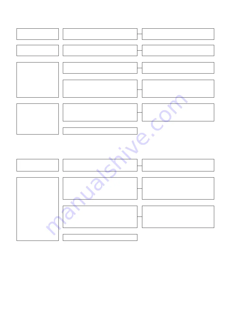
13.6 Paper feed table does not rise.
Check external
conditions.
Back door is open.
Close the back door.
Check while the TEST
mode is set.
Paper feed table works while the CHECK
key is set.
Check the back door, paper ejection, paper
stacking full or paper feed photo sensor.
Ў
Remove the cover on the
operator side and check
the status while setting
the TEST mode.
DC24V cannot be detected between pins 1
and 3 of the operation circuit board CN-10.
The switching power supply is faulty.
Ў
DC24V cannot be detected between pins 1
and 2 of the operation circuit board CN-15
when the CHECK key is pressed.
The MAIN PCB is faulty.
Ў
Remove the cover on the
anti-operator side and
check the status while
setting the TEST mode.
DC24V cannot be detected between both
ends of lifting motor when the CHECK key is
pressed.
Check the harness.
Ў
Elevation motor is out of order.
13.7 Main motor does not rotate.
Check external
conditions.
Back door is open.
Close the back door.
Remove the cover on the
operator side and check
the status while setting
the TEST mode.
DC5V cannot be detected between pins 1 and
3 of the operation circuit board CN-14 when
the RESET key is pressed to rotate the motor.
The operation circuit board is defective.
Ў
Rate voltage cannot be detected between pins
4 and 8 of speed control circuit board CN-3
when the RESET key is pressed to rotate the
motor.
Check the motor harness.
Ў
The MAIN PCB is faulty.
Summary of Contents for FC 10 PLUS
Page 1: ... 0 SERVICE MANUAL MBM TABLETOP COLLATOR MODEL FC 10 PLUS R e v 1 0 㻌 㻌 㻌 㻌 Sep 09 2016 ...
Page 7: ...6 䐟㻌 䐠㻌 䐡 䐢 䐣 䐤 䐥 䐦 䐧 䐨 䐩 䐪 䐫 䐯 䐰 䞣 䞢 䞡 䐲 䐱 䞧 䞦 䞥 䞤 䞨 䐬 䐭 䐮 䞪 䞩 䞫 1 2 Operation Panel ...
Page 20: ...19 ...
Page 21: ...20 6 MAIN PRINTED CIRCUIT BOARD ...
Page 22: ...21 7 Wiring Diagram ...
Page 33: ...32 Dismount the clutch holder Dismount the paper feed clutch ...
Page 35: ...34 Lift up the flat idler pulley and slip off the timing belt ...


