30
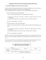
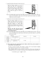
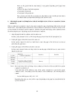
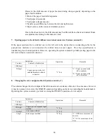
However, the shift amount of paper feed-out timing changes greatly depending on the
paper feed condition.
y
Wear of the paper feed roller/separator
y
Feed paper slip amount
y
Feed paper collapse amount
y
Transfer speed difference between the left and right towers
y
Slip at seizure of the connected transfer section
Due to the above factors, the shift amount may be different from what is calculated. Make
an adjustment referring to this numeric value.
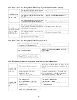
7. Ejecting paper to the left side without an external connector (System constant J)
If the paper ejection side is switched over to the left side in the status where a connecting cable for the
post-process machine is not connected, the collator does not eject paper. The above specification is
intended to prevent a misoperation. However, operating the system constant J permits ejecting paper to the
left side without an external connector.
Indication
Counter Contents
of
indication
Operation Remarks
1000 digit
J
-
10 digit
Paper ejection to the left
enabled/disabled without
connector
“3” key
“1”: Paper ejection to the
left is enabled.
“0”: Paper ejection to the
left is disabled.
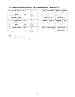
8. Changing the error output method (System constant y-1)
The collator changes the error output of the left connector at occurrence of an error. In some cases, however,
it may be necessary to reverse this ON/OFF operation depending on the device including the booklet maker.
Operating the system constant y permits reversing the ON/OFF operation of error output.
Indication
Counter Contents
of
indication
Operation Remarks
1000 digit
y
-
100 digit
Paper ejection response input
method
“2” key
10 digit
Error input method
“3” key
1 digit
Error output method
“4” key
“1”: OPEN at occurrence of
an error
“0”: 0 V at occurrence of an
error
Summary of Contents for FC-10
Page 2: ... 1 1 ...
Page 14: ...13 6 WIRING DIAGRAM ...
Page 15: ...14 7 CIRCUIT BOARD DIAGRAM 7 1 Operation board ...
Page 16: ...15 7 2 Speed control circuit board ...


