1
3
5
7
4
6
8
20
24
9
21
22
10
10
11
11
12
13
14
15
16
17
18
19
32
34
33
35
36
31
30
29
23
25
28
26
27
37
38
OPERATION
5
10
1.-
2.-
3.-
4.-
5.-
6.-
7.-
8.-
9.-
10.-
Connect hose and gun (use two wrenches to tighten the fittings). Don´t install the
spray tip yet.
Check the electrical service. Be sure the electrical installation is properly rated for
the sprayer and that the outlet you use is properly grounded. Use an extension cord
which has 3 wires of a minimum 4 mm size, and a maximum of 45 m long. Longer
lengths may affect sprayer performance.
Prepare the paint. Stir the paint to mix pigments. Strain the paint to remove particles
that could clog the filters or spray tip.
Put the suction tube into the pail container.
Lower the pressure setting by turning the pressure adjusting knob all the way
counterclockwise
Disengage the gun safety latch.
To prime the pump, hold a metal part of the gun firmly into a metal waste container.
Squeeze the trigger and hold it open, turn the ON/OFF switch to ON, and slowly
increase the pressure setting until the sprayer starts. Keep the gun triggered until all
air is forced out of the system and the paint flows freely from the gun. Release the
trigger and engage the gun safety latch.
Note:
If the pump is hard to prime, place a container under the pressure drain
valve and open it. When fluid comes from the valve, close it. Then disengage the
gun safety latch and proceed as in point 7.
Check all fluid connections for leaks. If any are found, follow the pressure relief,
before tightening connections.
Install the spray tip and tip guard. Be sure the gun safety latch is engaged.
Note:
your new sprayer was factory tested in lightweight oil which was left in to
protect pump parts. before using water-base paint, flush with mineral spirits followed
by clean water. Before using oil-case paint, flush with mineral spirits only.
Fill the packing nut with MBP - Packoil
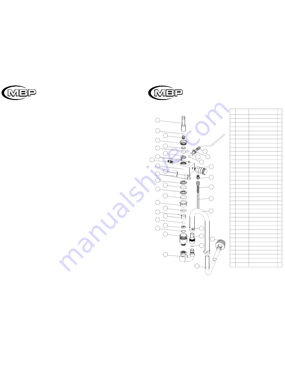
PART LIST DISPLACEMENT PUMP
REF.
102.210.00
CB0.110
080.230.00
102.200.03
102.200.04
CJT.044
102.200.05
102.200.01
102.200.06
CJT.045
102.200.07
102.200.08
080.200.10
080.200.11
CB0.111
102.220.00
102.200.09
102.200.02
CPA.218
CTB.036
CAR053
100.420.00
G.100.06
CJT.164
100.410.01
CEA.027
100.411.00
CNA.057
G.920.03
MAPM.203
102.310.00
CJT.175
102.300.01
CC0001
MAPM.202
102.320.00
D.910.00
DESCRIPTION
Rod
Ball
Seat ball
Tapón
Sleeve
O-ring
Packings
Body
Packings
O-ring
Sleeve
Joint
Sleeve-guide
Pin
Ball
Seat
Joint
Valve housing
Pin
Screw
Washer
Valve
Nipple
Joint
Body
Packing nut
Sensor
Nipple
Spring
Tube
Suction
Joint
Nipple
Clamp
Hose
Tube
Strainer
Nº
1
*3
4
5
6
*7
*8
9
*10
*11
12
13
14
15
*16
17
18
19
20
21
22
23
24
25
26
27
28
29
30
31
32
33
34
35
36
37
38
*
KIT 043:
Includes packings (up &
down) packing glands and balls.
Q
1
1
1
1
1
1
1
1
2
2
1
1
1
1
1
1
1
1
2
2
2
1
1
1
1
1
1
1
1
1
1
1
1
2
1
1
1