Chapter 3
Device views
11
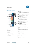
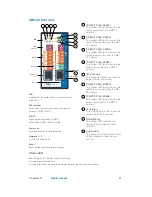
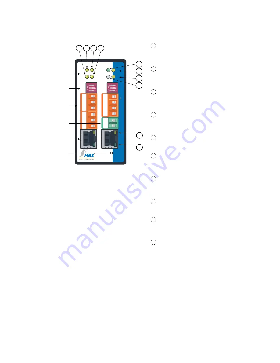
1
TX (MS/TP TxD, RS232)
This yellow LED lights up when the
router sends data to the MS/TP
network.
2
RX (MS/TP RxD, RS232)
This yellow LED lights up when the
router receives data from the MS/
TP network.
3
RX (MS/TP RxD, RS485)
This yellow LED lights up when the
router receives data from the MS/
TP network.
4
TX (MS/TP TxD, RS485)
This yellow LED lights up when the
router sends data to the MS/TP
network.
5
PWR. (Power)
This green LED lights up when the
power supply is activated.
6
RX (MS/TP RxD, RS485)
This yellow LED lights up when the
router receives data from the MS/
TP network.
7
TX (MS/TP TxD, RS485)
This yellow LED lights up when the
router sends data to the MS/TP
network.
8
ST. (Status)
This multi-coloured LED shows the
system status of the router.
9
10/100 MBit/s
This yellow LED indicates the
speed of the connection to the
network.
10
Link/Activity
This green LED indicates the status
of the network connection and
activity.
Status LED:
Red for approx. 6 s: Self test after switching on
Flashing green: Normal state
Flashing alternately red and green: during the reset process (see chap. Reset)
Reset
LAN
1
LAN
2
B+
–
PWR
+
A-
GND
S3
S2
S1
TX
RX
ST.
PWR.
UBR-02
BACnet Router
TX
RX
TX
RX
RS485
RS485
RS232
RS232
RS485
TXD
RXD
GND
B+
A-
GND
S3
S2
S1
B+
A-
Shld
AGND
+24
GND
B+
A-
GND
TXD
RXD
GND
8
7
5
6
4
3
1
2
Link/Activity
10
10/100 MBit/s
9
Netzwerk
1 + 2
Netzteil
MS/TP
DIP-
Schalter
LED
Reset
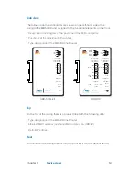
UBR-02 front view
LED
Indication of the system status of the router with
eight LEDs
DIP switches
Activation of bus termination and network bias
resistors (COM1, COM3)
MS/TP
Right: Weidmüller socket (COM1)
Left: RS485 (COM3), RS232 (COM2)
Power unit
2-pole connection to voltage supply
Network 1 + 2
2 x RJ45 sockets (LAN)
Reset
Reset button to restore factory settings
Summary of Contents for UBR-01 MK II
Page 57: ......


