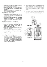
54. If required, install the bushings (#10), extension
plates (#9), and 1” socket head cap screws (#37) to
the sides of baseplate housing using LOCTITE #767
antisieze compound on the bushings and bolt
threads.
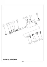
Control Head Assembly Procedure
Refer to Control Head Assembly, page 30.
1.
Clean and dry all parts to be assembled.
2.
If required press the slide bushing (#4) into the
control housing (#7).
3.
Press the hydraulic seal (#5) onto the piston shaft
(#12).
Be careful to orient the seal lip to face away
from the guide ring groove. Tip: Use approved
hydraulic oil to lubricate the seal inside diameter
to ease assembly. See Maintenance Section for
type of hydraulic oil.
4.
Assembly the bearing guide ring (#10) to piston
shaft (#12) groove behind the hydraulic seal (#5).
Note: Use hydraulic oil to lubricate guide ring &
hydraulic seal before assembling into control
housing.
5.
Slide the piston shaft assembly (#12) into the control
head housing (#7), being careful not to damage guide
ring or hydraulic seal when entering control housing.
6.
Install O-ring (#3) and hydraulic fitting (#1) to
adapter nut (#14).
7.
Install adapter nut assembly (#14) into control head
housing (#7).
Note: Use hydraulic oil to lubricate guide ring &
hydraulic seals before assembling into seal cap.
8.
Assemble guide ring (#11), hydraulic seal (#9) and
shaft wiper seal (#8) into seal cap (#13).
9.
Install washer seal (#2) and seal cap assembly
(#13) over piston shaft (#12) and into control head
housing (#7).
10. Assemble socket pipe plugs (#15 & 16) into control
head housing (#7) using LOCTITE #565 pipe sealant.
11. Install
hydraulic
fitting
(#6)
into
control
head
housing.
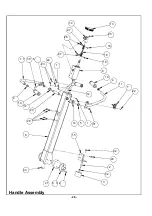
Handle Assembly Procedure
Refer to Handle Assembly, page 28.
1.
Install shift linkage (#16) to control head (#9) with
shoulder bolt (#18), washer (#27) and lock nut (#26).
2.
Assemble shift bracket (#10) to shift linkage (#16)
with shoulder bolt (#18), washer (#27) and lock nut
(#26)
3.
Install the control head assembly (#9) into the
handle tube (#8) with four flange lock screws (#28).
4.
Install plain bearings (#14) into each side of handle
tube (#8).
5.
Install control shaft (#20) into handle tube (#8) and
secure with retaining rings (#5).
Note: Control shaft can be install for either right or left
hand operation.
6.
Install control handle (#17) to control shaft (#20) and
secure by driving spiral pin (#30) thorough handle
hub & control shaft.
7.
Assemble shift bracket (#10) to control shaft (#20)
with flange lock screws (#25).
8.
Install throttle lever (#7) to handle tube (#8) with flat
head screw (#22), lock washers (#24) and hex nuts
(#23).
9.
Install handle bars (#11 & 12) to handle tube (#8)
using flange lock screws (#31).
10. Install tube cap (#13) to handle tube (#8) with self
tapping screws (#1).
11. Install bumper bracket (#15) to handle tube (#8)
using flange lock screws (#29).
12. Assemble threaded rod (#2), hex nuts (#32) and
handle bumper (#3) to bumper bracket (#15).
13. Assemble shock mounts (#21) to handle tube (#8)
with flange lock screws (#33).
14. Assemble spindle mounts (#6) to shock mounts
(#21) with flat head screws (#34).
Refer to Main Assembly, page 22.
15. Install handle mounts (#4) onto handle assembly
spindles.
16. Secure handle assembly to engine deck with four
hex head flange screws (#27).
Final Assembly
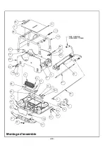
Refer to Main Assembly, page 22.
1.
Place engine (#2 or #15) on engine deck (#20) and
align with engine mounting holes.
Refer to engine pages (Gasoline or Diesel)
2.
Install four bolts, lock washers and washers (#11,
#14 & #15) or (#29, #30 & #31) through the engine
block into engine deck.
Note: If engine does not sit flat on engine deck, shim
as needed.
Refer to DIESEL ENGINE ASSEMBLY, page 38.
3.
Secure battery box mounting brackets (#21) to engine
deck using four hex head flange screws (#28).
4.
Assemble battery box (#19) to shockmounts (#18)
with four hex head cap screws (#34) and lockwashers
(#37).
- 17 -
Summary of Contents for 2900280
Page 10: ...6...
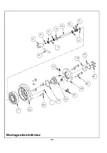
Page 31: ...4 15 10 3 5 9 8 7 11 19 18 14 6 2 0 21 22 13 16 17 1 22 2 12 Montage arbre inf rieur 26...
Page 35: ...16 6 15 7 12 10 5 3 14 1 8 13 11 9 2 4 Boitier de commande 30...
Page 42: ...NOTES 37...
Page 43: ...NOTES 38...
Page 52: ...6...
Page 73: ...4 15 10 3 5 9 8 7 11 19 18 14 6 2 0 21 22 13 16 17 1 22 2 12 Montage arbre inf rieur 26...
Page 77: ...16 6 15 7 12 10 5 3 14 1 8 13 11 9 2 4 Boitier de commande 30...
Page 84: ...NOTES 37...
Page 85: ...NOTES 38...
Page 108: ...22 Montage d ensemble 6 1 66 0 3...
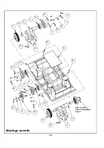
Page 110: ...24 6 2 5 6 7 66 0 3 Montage semelle...
Page 112: ...26 Montage arbre inf rieur...
Page 114: ...28 Handle Assembly...
Page 116: ...30 Boitier de commande...
Page 118: ...32 6 0 1 1 21 6 5 48 5 0 6 06 1 21 3 Gasoline Engine Assembly...
Page 120: ...34 Diesel Engine Assembly...
Page 123: ...37 NOTES...
Page 124: ...38 NOTES...

