4
6
5
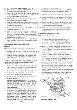
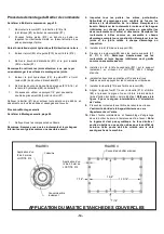
FIGURE 6
ENGINE VIEW:
3 2 1
5.
Remove electrical tape from positive battery cable
(#11) and assemble to engine starter.
6.
Remove electrical tape from negative battery cable
(#10) and assemble under head of engine mounting
bolt (#29).
7.
Secure engine ignition box to mounting bracket
(#14) using three 6mm bolts (#35).
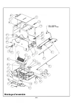
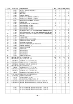
Refer to Main Assembly, page 22.
8.
Assemble rollcage (#19) to engine deck (#20) with
four hex head cap screws (#32), lockwashers (#34)
and washers (#35).
9.
Using main lift hook on roll cage, lower engine deck
assembly onto baseplate.
Use care to route
hydraulic hose through engine deck and up handle
tube.
Refer to engine pages (Gasoline or Diesel)
10. Slide belt (#3 or #4) onto clutch (#4 of #7).
11. Install four bolts (#32) lockwashers (#34) and
washers
(#35)
through
engine
deck
into
shockmounts on bottom plate.
12. Refer to the
Belt Adjustment
section of this manual
to complete assembly.
13. Secure hydraulic line (#21) to control head fitting.
14. Bleed the hydraulics according to the
Bleeding and
Adjustment of Hydraulic Controls
section of this
Manual.
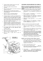
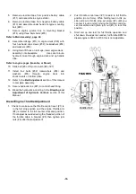
Diesel Engine Throttle Adjustment
1.
Check to make sure the throttle control lever (#1) is
in the full stop position and the engine throttle arm
(#4) is rotated to the full counter clockwise position.
If not adjust as needed using the threaded portion of
the throttle cable in bracket (#5) then tighten jam
nuts (#6) after final adjustment.
2.
Push throttle control lever (#1) forward to full throttle
position (do not force). While holding lever in this po-
sition screw in throttle stop set screw (#2) until you
can feel it touch or start moving the throttle control le-
ver. Assemble and tighten jam nut (#3) to lock this
position.
3.
Start unit up and test for full throttle operation and
shut down. Re-adjust as needed, full throttle RPM for
diesel engine is 3600 to 3700, this is not adjustable.
- 18-
Summary of Contents for 2900280
Page 10: ...6...
Page 31: ...4 15 10 3 5 9 8 7 11 19 18 14 6 2 0 21 22 13 16 17 1 22 2 12 Montage arbre inf rieur 26...
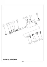
Page 35: ...16 6 15 7 12 10 5 3 14 1 8 13 11 9 2 4 Boitier de commande 30...
Page 42: ...NOTES 37...
Page 43: ...NOTES 38...
Page 52: ...6...
Page 73: ...4 15 10 3 5 9 8 7 11 19 18 14 6 2 0 21 22 13 16 17 1 22 2 12 Montage arbre inf rieur 26...
Page 77: ...16 6 15 7 12 10 5 3 14 1 8 13 11 9 2 4 Boitier de commande 30...
Page 84: ...NOTES 37...
Page 85: ...NOTES 38...
Page 108: ...22 Montage d ensemble 6 1 66 0 3...
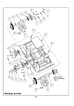
Page 110: ...24 6 2 5 6 7 66 0 3 Montage semelle...
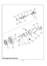
Page 112: ...26 Montage arbre inf rieur...
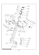
Page 114: ...28 Handle Assembly...
Page 116: ...30 Boitier de commande...
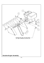
Page 118: ...32 6 0 1 1 21 6 5 48 5 0 6 06 1 21 3 Gasoline Engine Assembly...
Page 120: ...34 Diesel Engine Assembly...
Page 123: ...37 NOTES...
Page 124: ...38 NOTES...

