26. Lubricate the helix pin carrier/shift shaft assembly
with exciter oil and slide into the input shaft and
install the dowel pin (#11).
Note: Helix pin carrier MUST slide freely in input shaft.
27. Slide the helix pin/carrier to the middle of the helix
and orient the dowel pin parallel with the bottom of
the baseplate housing (#15).
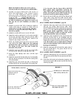
28. Align the timing marks on both gears and slide the
input gear over the helix pin/carrier and into mesh
with the gear on the idler shaft. Note position of
exciter weights (both weights in the down position)
See the figure #5 for setting the gear timing.
29. Install the other exciter weight (#17) to the input shaft
(#16) with two socket head cap screws (#24) using
LOCTITE #243 thread locker sealant on the threads
and torque the cap screws to 30 ft.-lbs.
Be careful to
use a small amount of thread locker to avoid
dripping it into the helix pin carrier bearings at
installation.
30. Check the gear timing to assure free motion of the
shift shaft/helix pin carrier within the helix of the
input shaft for the full range of motion from one end
of the helix to the other.
Refer to LOWER SHAFT ASSEMBLY, page 30. for steps
#32 thru #42.
Note: The seals (#6), guide ring (#4), and gaskets (#17
and #18) should be replaced as a set. MBW
recommends purchasing rebuild kit #17368 for ease
of repairs (Seals are pre-assembled to the spool).
31. If rebuild kit #17368 was purchased, skip to step #34.
32. Assemble the new seals (#6) to the shift spool (#15).
Note the orientation of the seal lips. Hint: use
hydraulic oil to lubricate the seal inner diameter
before pressing onto the spool. Beware the slot
cut on the shift spool. It may be sharp. Press the
seal on “WITH” the slot and NOT “ACROSS” the
slot.
33. Thread the shift spool with seals onto the shift shaft
(#10).
Note the left had thread.
34. Assemble the new guide ring (#4) to the shift spool.
35. Install a new mount gasket (#17) onto the hydraulic
housing (16).
36. Lubricate the inside of the hydraulic housing (#16)
and the seal lips with hydraulic oil.
See Maintenance
section for hydraulic fluid type.
37. Install the hydraulic housing over the hydraulic seals
and guide ring.
Be careful not to damage the guide
ring and hydraulic seals during installation.
38. Secure the mount plate (#20) over the hydraulic
housing (#16) to the input shaft cover (#12) with the
four flanged cap screws (#22) using LOCTITE #243
thread locker sealant on the threads and torque the
cap screws evenly in stages to 13 ft.-lbs.
Make sure the bleeder screw port (#14) is in the
vertical position.
39. Install the gasket (#18) and cover (#19) to the
hydraulic housing (#16) with four hex head flange
screws (#21) using LOCTITE #243 thread locker
sealant on the threads and torque the cap screws to
76 in-lbs.
40. Install the 90 degree fitting (#13) into the port on the
hydraulic housing (#16).
41. Install the bleeder screw (#14) loosely into the port
fitting of the hydraulic housing.
42. Install the socket head pipe plug (#25) into the oil
drain port using LOCTITE #565 pipe sealant.
43. Pour in the exciter oil.
Use only MBW Ground
Pounder Exciter Oil. The amount of exciter oil
required is shown in the FLUID LEVELS section
of this manual.
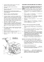
44. Install the baseplate cover (#13) using LOCTITE #515
gasket maker on the lip of the mounting surface and
secure with twenty hex head flange screws (#22)
using LOCTITE #243 on the threads.
See the figure
#4 for LOCTITE #515 gasket maker application.
45. Install the key (#6) into the input shaft (#16).
46. Install the pulley (#19) with the longer hub shoulder
toward the baseplate housing.
47. Install the pulley mount washer (#14) and secure it
to the input shaft with the hex head flange screw
(#22) using LOCTITE #243 thread locker sealant on
the threads.
Refer to engine pages (Gasoline or Diesel)
48. Install the v-belt (#3 or #4) to the pulley of the
baseplate assembly.
Refer to Main Assembly, page 22.
49. Install the side cover (#12) on the pulley side of the
baseplate housing and secure with six hex head
flange screws (#22) using LOCTITE #243 thread
locker sealant.
50. Install the bellows (#3) into the bellows mount plate
(#14) and secure it to the baseplate with four hex
head flange screws (#23). Note spacer washers
(#28) between plates (#14).
51. Connect the hydraulic line (#21) to the 90 degree
fitting on the hydraulic housing.
52. Install the grommet (#2) into the hydraulic guard
(#13).
53. Guide the hydraulic line(#21) through the grommet
(#2) in the hydraulic guard (#13) and secure the
guard to the hydraulic side of the baseplate with the
four hex head flange screws (#22).
Set the side
cover (#12) off to the side until bleeding and
final assembly is done. The exciter is now ready
for final assembly.
- 16 -
Summary of Contents for 2900280
Page 10: ...6...
Page 31: ...4 15 10 3 5 9 8 7 11 19 18 14 6 2 0 21 22 13 16 17 1 22 2 12 Montage arbre inf rieur 26...
Page 35: ...16 6 15 7 12 10 5 3 14 1 8 13 11 9 2 4 Boitier de commande 30...
Page 42: ...NOTES 37...
Page 43: ...NOTES 38...
Page 52: ...6...
Page 73: ...4 15 10 3 5 9 8 7 11 19 18 14 6 2 0 21 22 13 16 17 1 22 2 12 Montage arbre inf rieur 26...
Page 77: ...16 6 15 7 12 10 5 3 14 1 8 13 11 9 2 4 Boitier de commande 30...
Page 84: ...NOTES 37...
Page 85: ...NOTES 38...
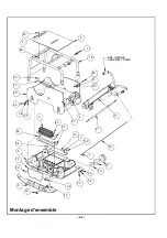
Page 108: ...22 Montage d ensemble 6 1 66 0 3...
Page 110: ...24 6 2 5 6 7 66 0 3 Montage semelle...
Page 112: ...26 Montage arbre inf rieur...
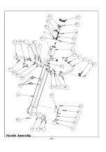
Page 114: ...28 Handle Assembly...
Page 116: ...30 Boitier de commande...
Page 118: ...32 6 0 1 1 21 6 5 48 5 0 6 06 1 21 3 Gasoline Engine Assembly...
Page 120: ...34 Diesel Engine Assembly...
Page 123: ...37 NOTES...
Page 124: ...38 NOTES...

