MBW 473 Manual English V5.0
47
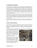
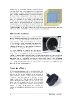
The user must therefore determine this effect experimentally for the conditions used. In the example
installation shown above, the RP2 measuring head and the chamber door are thermally coupled to
allow for optimum dissipation of heat generated by the measuring head. At equlibrium, the generator
will establish a thermal equilibrium within the complete system so that temperature stability is
optimized and gradients are minimized.
Whereas the RP2 head-mounted temperature probe (PRT) can be used for the measurement of
temperature in most measurement situations, in some chamber conditions a short extension cable
may be advisable
to thermally ‘decouple’ the PRT from the measuring head. Especially at low RH
conditions, where the mirror temperature can be much lower than the chamber temperature, the
heating of the measuring head can cause temperature errors. Therefore, consideration of this possible
effect must be included within uncertainty budgets. In calibration laboratories where the lowest
possible uncertainties are required, the implementation of continuous multi-point temperature
measurement allows the user to determine gradients dynamically. In such small chambers, four or six
PRTs arranged around the working volume is sufficient according to IEC 60068.
When comparing (for example) RH probes to the RP2 probe mounted in an RH generator chamber, it
is reccomended that there is at least 10mm of clearance between the probes to minimise any thermal
effects. If there is poor air movement within the chamber, separation may need to be greater than
10 mm.
In all temperature related effects recording and analysing data, understanding cause and effects, and
applying best measurement practises are essential in resolving best measurement capabilty and low
uncertainty.
Condensation
If the RP2 probe is installed through the chamber ports of an RH generator working at high tempera-
ture, a thermal gradient through the RP2 may occur and the probe may be at a slightly lower tempera-
ture than the chamber. This may cause condensation to form on the outer body of the RP2 probe. As
a result, the measured dew point values will be incorrect. It is even possible that condensation on the
head will cause a short circuit. To avoid such problems, make sure that the RP2 probe is inserted as
far as possible into the chamber volume. More advanced RH generators feature heated doors which
prevent condensation.
When measuring in a chamber where conditions are changing (ramp up phase) the
thermal mass of the dew point measuring head may mean that its temperature is below
the dew point in the chamber and condensation occurs. Use the ‘Measuring Head
Tem
perature’ parameter of the 473 to avoid this effect.
Summary of Contents for 473-RP2
Page 1: ...Operation and Maintenance Manual V5 0 Dew Point Mirror 473...
Page 2: ......
Page 4: ...ii MBW 473 Manual English V5 0...
Page 8: ...2 MBW 473 Manual English V5 0...
Page 10: ...4 MBW 473 Manual English V5 0...
Page 14: ...8 MBW 473 Manual English V5 0 SH2 SHX Fan Fan...
Page 30: ...24 MBW 473 Manual English V5 0...
Page 68: ...62 MBW 473 Manual English V5 0...
Page 69: ...MBW 473 Manual English V5 0 63 11 Drawings 11 1 Display Unit Side View...
Page 70: ...64 MBW 473 Manual English V5 0 Front View Back View...
Page 71: ...MBW 473 Manual English V5 0 65 11 2 Measuring Heads RP2 SH2...
Page 72: ...66 MBW 473 Manual English V5 0 SHX SH3...
Page 73: ...MBW 473 Manual English V5 0 67...
Page 74: ...68 MBW 473 Manual English V5 0...

