MBW973-SF6_MANUAL_E_V3.1
9
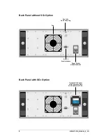
Power Connection
The AC power cord is connected to the power socket on the instrument back panel. The power
socket also includes the power switch. The power supply voltage is 100-120 VAC /
200-240 VAC at 50 to 60Hz. The power supply is internally fused and will automatically switch
off in case of an overload. To restart the power supply, the instrument main switch must be
switched to
0
and
I
again.
SO
2
-Module
When fitted, the SO
2
module is mounted to the back panel of the 973 which allows the SO
2
sen-
sor to be easily replaced by the user. The sensor has to be replaced every two years. The cali-
bration and replacement dates are indicated on the SO
2
module.
Gas Inlet Quick Coupling
The sampling line is connected to the sample gas inlet. If the instrument is not in use the inlet
should be protected with the blue cover.
RS-232 Serial Interface Connector
The RS-232 connector is used when connecting the 973 to a computer. Use the supplied 9 pin
1:1 cable to connect the 973 to a desktop or laptop computer. This cable has a male connector
on one end and a female connector on the other end. It is most often referred to as a serial ex-
tension cable.
Fan
When the 973 is switched on, the cooling fan always runs independent of the ambient and in-
strument temperatures.
Summary of Contents for 973-SF6
Page 2: ......
Page 6: ...2 MBW973 SF6_MANUAL_E_V3 1...
Page 8: ...4 MBW973 SF6_MANUAL_E_V3 1...
Page 14: ...10 MBW973 SF6_MANUAL_E_V3 1...
Page 20: ...16 MBW973 SF6_MANUAL_E_V3 1...
Page 32: ...28 MBW973 SF6_MANUAL_E_V3 1...
Page 38: ...34 MBW973 SF6_MANUAL_E_V3 1...
Page 48: ...44 MBW973 SF6_MANUAL_E_V3 1...

