EM100xx Control Module - Installation / User Manual
14
Copyright 2010 MBW Technologies, LLC All Rights Reserved
to operate. If the inputs differ by more than 10% the lever will be
considered failed. The select lamp will begin a fast flash indicating a
critical failure and the drive train in question will be held at the engine
idle state. If the throttle head wiring is defective or disconnected the
system will indicate a critical failure and enter into the system error
reaction state. If the network communications connection from the
EM100 to the Yanmar Control Network is lost or broken the system
will indicate a critical failure and enter into the system error reaction
state.
System Calibration
To calibrate the EM100xx module with the mating throttle head,
perform the following steps.
STOP: Your Throttle and Shift System has been calibrated from
the factory. Proceed with the steps below only if the
EM100x module or throttle controls have been replaced.
*** Proceed With Caution ***
1. With the control powered off, move the
PORT
gear lever to the
full forward position; the throttle lever to idle. In the case of a
multi-engine application move all throttles to the idle position.
2. Power the system, while pressing and holding the select
switch. The control is now in the calibrate mode. Select lamp
“Off”
3. Move all throttle levers to the wide open throttle position. Press
the select switch to enter the position of the throttle lever(s).
The green lamp on the select switch will flash momentarily
when data is entered.
4. Move all throttle levers to the idle position. Press the select
switch to enter the position of the throttle lever(s). The green
lamp on the select switch will flash momentarily when data is
entered.
5. Power the system off and back on.
6. The control is now calibrated.
7. Verify calibration by viewing the %Throttle display on the
i5601E display. The display should read 100% for each
throttle when the respective throttle lever is a WOT. The
display should read 0% for each throttle when the respective
throttle lever is at idle.
EM100xx Control Module – Installation / User Manual
Copyright 2010 MBW Technologies, LLC All Rights Reserved
3
Table of Contents
Product Overview ...................................................................................................... 4
Components ................................................................................................................. 4
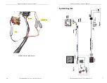
System Diagram .......................................................................................................... 7
Installing the System ................................................................................................ 9
System Operation ................................................................................................... 12
Engine Synchronization ....................................................................................... 13
Start-in-Gear Protection ...................................................................................... 13
Station Transfer ....................................................................................................... 13
Throttle Failure Detection .................................................................................. 13
System Calibration ................................................................................................. 14
Technical Specifications ....................................................................................... 15
EM100xx Module ............................................................................................................ 15
EM100xx Data Transmitted ............................................................................... 15


