background image

EM100xx Control Module - Installation / User Manual 


12


Copyright 2010 MBW Technologies, LLC All Rights Reserved 

System Operation 

For single station applications, the control will auto select when the 
following conditions are met; 

1)  System is powered 
2)  Gear lever is neutral 
3)  Throttle lever is less than 2% throttle. 
 

 For dual station applications, station select will occur when the 
following conditions are met;  

1) System is powered. 
2) Gear Lever is neutral 
3) Throttle lever is less than 2% throttle. 
4) Select switch for desired station is pressed. 
 

When these conditions are met the select lamp (green lamp) will 
activate indicating the station is selected. If the control is not selected 
the select lamp will flash. The Yanmar System will allow the engine to 
start if the throttle head is not selected but will not allow the engine to 
throttle up until the control is selected. If the select lamp is flashing 
simply move the throttle and gear levers to the idle/neutral positions. 
The select lamp will stop flashing and indicate a steady green 
indication. The control is now selected and operational.  
 
The EM100xx Interface Module communicates to the Yanmar Drive 
Train Control Module  via the CANBus network.  The Yanmar Control 
System will lock-out engine start under the following conditions;  

1) The station is selected. 
2) The gear lever is requesting a gear position other than neutral. 
3) The throttle lever is requesting a throttle > 5%.    


EM100xx Control Module  – Installation / User Manual 


  Copyright 2010 MBW Technologies, LLC All Rights Reserved


 5


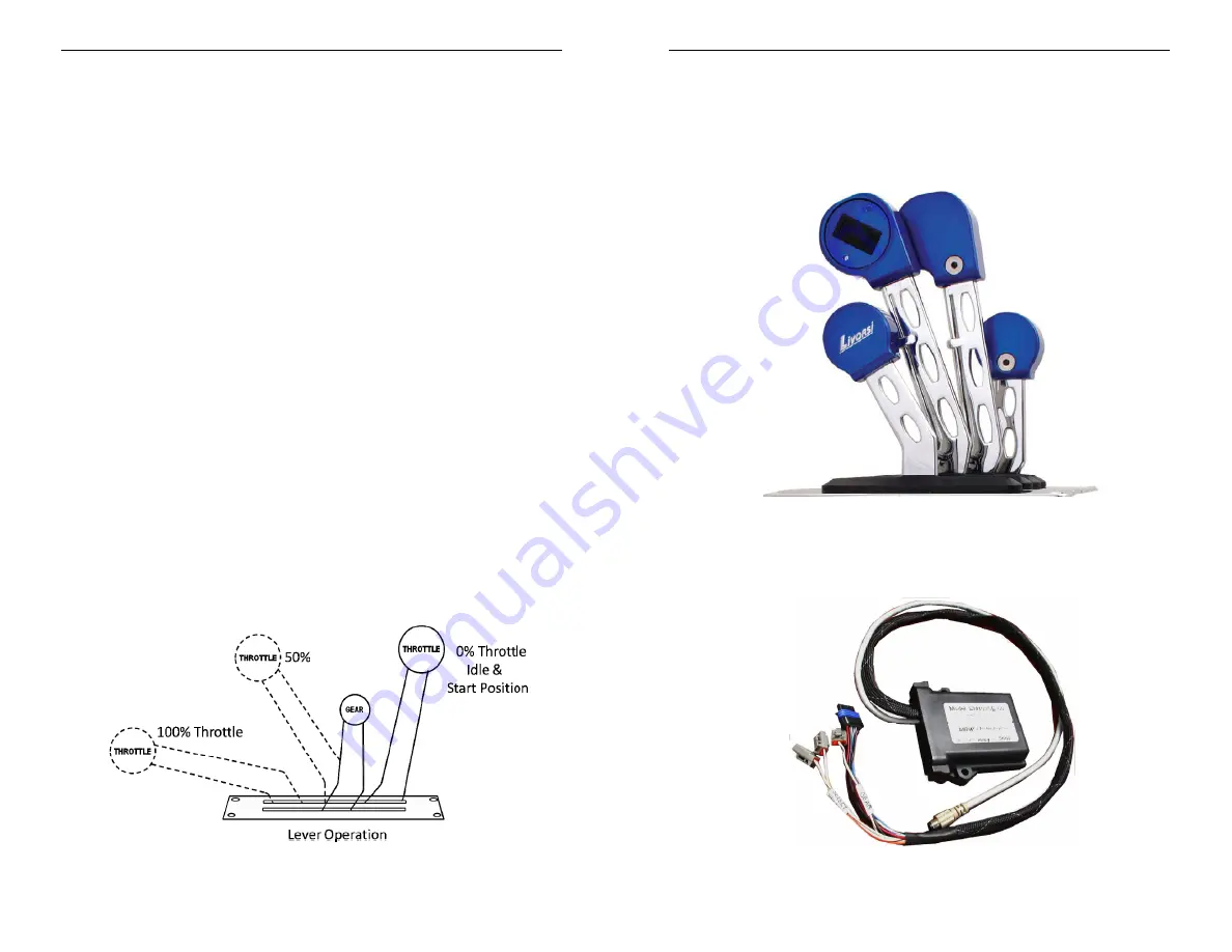
EM100xx – Electronic Module 

Dual Engine Throttle Head  - Customer Specified 

Summary of Contents for CH104 Series

Page 1: ...Suite 1 Harleysville PA 19438 Tech Support 267 932 8573 x341 Fax 267 284 1336 Email sales mbwtech com Email support mbwtech com OR Contact your local Yanmar Dealer Installation User Manual EM100xx In...

Page 2: ...MBW Within this period MBW will at its sole option repair or replace any electrical cable or connector that fails in normal use and returned to MBW freight prepaid within the warranty period MBW is n...

Page 3: ...ication move all throttles to the idle position 2 Power the system while pressing and holding the select switch The control is now in the calibrate mode Select lamp Off 3 Move all throttle levers to t...

Page 4: ...hen the throttles are 20 throttle AND the throttle levers are matched within 5 of one another Should the throttle levers be mis matched by 5 the engine speed for each engine will be defined by the lev...

Page 5: ...lash The Yanmar System will allow the engine to start if the throttle head is not selected but will not allow the engine to throttle up until the control is selected If the select lamp is flashing sim...

Page 6: ...le Installation User Manual 6 Copyright 2010 MBW Technologies LLC All Rights Reserved EM100xx Control Module Installation User Manual Copyright 2010 MBW Technologies LLC All Rights Reserved 11 EM100DE...

Page 7: ...anual 10 Copyright 2010 MBW Technologies LLC All Rights Reserved EM100SE Series Interconnect Select Switch Gear Throttle EM100xx Control Module Installation User Manual Copyright 2010 MBW Technologies...

Page 8: ...turer installation manual Verify engines are bonded to battery return and that battery banks are tied to battery return Verify engine blocks are connected battery bank ground 2 Locate placement area f...

Reviews: