14 of 68
2.1.
IDENTIFICATION DATA OF THE
MACHINE
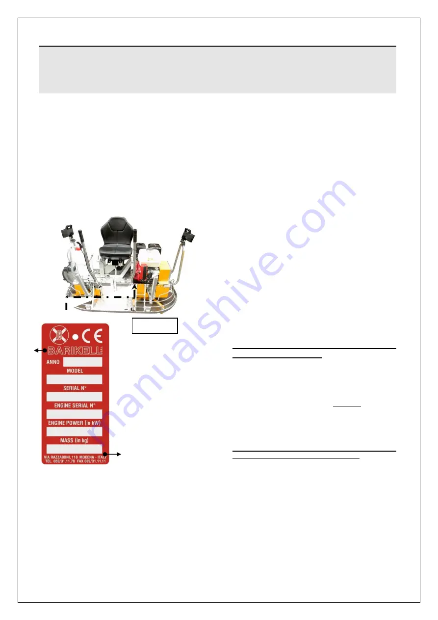
In order to ensure proper identification of the
machine, please refer to the serial number
stamped on the invoice and the data
imprinted on the manufacturer's plate bearing
the CE marking symbol attesting to its
conformity to the directives applicable.
The plate includes the following required
information:
●
Manufacturer’s name and address
(1)
●
CE Marking (2)
●
Year of construction (3)
●
Type designation (4)
●
Serial number (5)
●
Motorization number (6)
●
Motorization power (7)
●
Mass in kg (8)
2.2.
INTENDED USE
The double trowel machine "
MK8-75
” is
designed and manufactured to perform
finishing (troweling) of concrete and asphalt
floors of sheds, car parks, cycle paths,
parking areas, sidewalks, etc. To make this
kind of the machining operations the machine
is equipped with two rotors: One of them is
rotates right and the other rotates left.
The engine and the operator's seat are fixed
to a frame connected to both rotors.
The adjustable seat is located at a very low
height which allows you to create different
advantageous conditions for processing:
●
A higher flatness of the floor surface
(thanks to a lowering of the machine´s
centre of gravity).
●
An excellent view of the inspection of
the processing.
All steering parts (levers, joints, drive
shaft, reducers) are protected by a tunnel
whose
purpose
is
to
prevent
the
accumulation
over
time
of
cement
deposits that can cause a more rapid
damage to mechanical components.
The machine may only be used by
professional operators.
2.3.
PROHIBITED USE
Any use other than what is explicitly stated in
PAR. (§ 2.2) and implemented differently or
contrary to what is stated in this publication
represents a possible
misuse
. The
manufacturer
accepts
no
responsibility
resulting from improper use which may lead
to
personal
injury
and
any
system
malfunctions.
IMPROPER USE IS CONSTITUTED BY THE
FOLLOWING 'PROHIBITED’ ACTIVITIES:
-
THE
MACHINE
IS
USED
IN
AN
EXPLOSIVE
ENVIRONMENT
(THIS
FACILITY IS NOT IN COMPLIANCE WITH
ATEX 2014/34/EU).
-
OTHER SYSTEMS AND/OR EQUIPMENT
ARE ADDED EVEN IF THEY ARE NOT
INCLUDED BY THE MANUFACTURER IN
THE EXECUTIVE PROJECT.
-
THE MACHINE IS ATTACHED TO POWER
SOURCES
OTHER
THAN
THOSE
SPECIFIED BY THE MANUFACTURER.
-
THE MACHINE IS USED FOR A PURPOSE
OTHER THAN THAT INTENDED AND
SHOWN IIN THIS PUBLICATION.
!
CAUTION
Do not remove, damage or modify the machine identification information on the
machine. In case the data become unreadable immediately contact the
manufacturer.
Figure 2.1
2
1
4
5
1
3
6
7
8
5
4
2
6
7
3
2
Summary of Contents for MK8-75
Page 19: ...19 of 68...
Page 20: ...20 of 68...
Page 21: ...21 of 68...
Page 22: ...22 of 68...
Page 23: ...23 of 68...
Page 38: ...38 of 68 5 5 LAYOUT OF CONTROLS...
Page 50: ...50 of 68 ATTACHED WIRING DIAGRAM...
Page 51: ...51 of 68 6 5 PARTS LIST...
Page 52: ...52 of 68...
Page 53: ...53 of 68...
Page 54: ...54 of 68...
Page 55: ...55 of 68...
Page 56: ...56 of 68...
Page 57: ...57 of 68...
Page 58: ...58 of 68...
Page 59: ...59 of 68...
Page 60: ...60 of 68...
Page 61: ...61 of 68...
Page 62: ...62 of 68...
Page 63: ...63 of 68...
Page 64: ...64 of 68...
Page 65: ...65 of 68...
Page 66: ...66 of 68...
Page 67: ...67 of 68...


