27 of 68
a
b
c
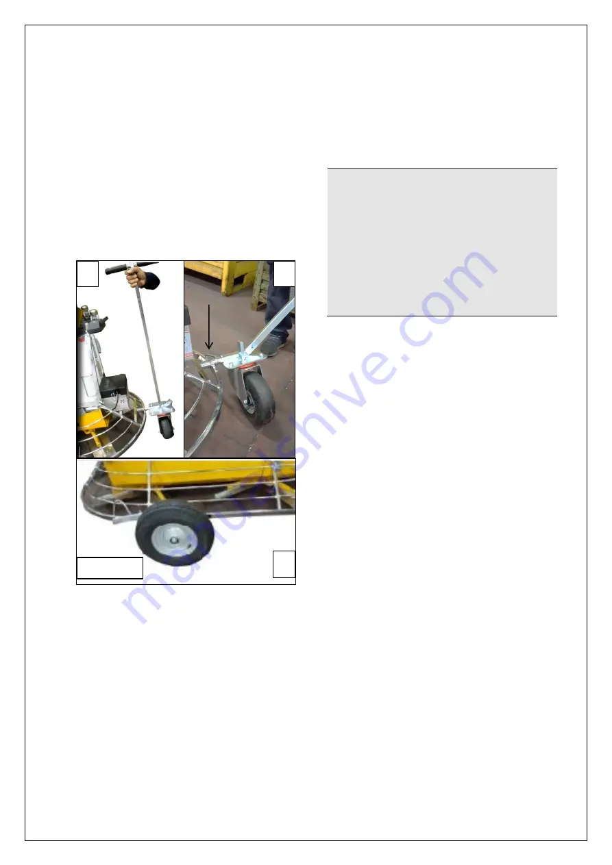
Horizontal displacement
A handling trolley is provided along with the
machine with the purpose to support the
machine and handle it safely. The trolley is
equipped with a handle with a final grip
through which 4 wheels are mounted on the
machine: 2 small and 2 big wheels that make
the machine easily transportable by ground.
1. Insert the small wheel of the trolley by
means of the handle on the cavity at the
bottom of the machine (fig. 3.5, a).
2. Secure it with the appropriate lock (fig.
3.5, b).
3. Perform the operation on both sides of
the machine.
4. The two large wheels (fig. 3.5, c)
belonging to the handling device should
be mounted using the handle of the trolley
and attached to the machine frame.
!
CAUTION
Pay particular attention to the task
of removing the handling trolley of
the machine because it tends to
undergo a dangerous kickback that
can cause its jolting creating
dangerous situations for those
involved in the operation.
There is a residual risk of impact as
indicated in the table of residual
risks.
c
Figure 3.5
Summary of Contents for MK8-75
Page 19: ...19 of 68...
Page 20: ...20 of 68...
Page 21: ...21 of 68...
Page 22: ...22 of 68...
Page 23: ...23 of 68...
Page 38: ...38 of 68 5 5 LAYOUT OF CONTROLS...
Page 50: ...50 of 68 ATTACHED WIRING DIAGRAM...
Page 51: ...51 of 68 6 5 PARTS LIST...
Page 52: ...52 of 68...
Page 53: ...53 of 68...
Page 54: ...54 of 68...
Page 55: ...55 of 68...
Page 56: ...56 of 68...
Page 57: ...57 of 68...
Page 58: ...58 of 68...
Page 59: ...59 of 68...
Page 60: ...60 of 68...
Page 61: ...61 of 68...
Page 62: ...62 of 68...
Page 63: ...63 of 68...
Page 64: ...64 of 68...
Page 65: ...65 of 68...
Page 66: ...66 of 68...
Page 67: ...67 of 68...


