31 of 68
!
CAUTION
It is recommended to connect the
battery cable correctly.
Please refer to the manual of the
manufacturer of the engine that is an
integral part of this publication.
●
Rotate upward the lighting devices.
●
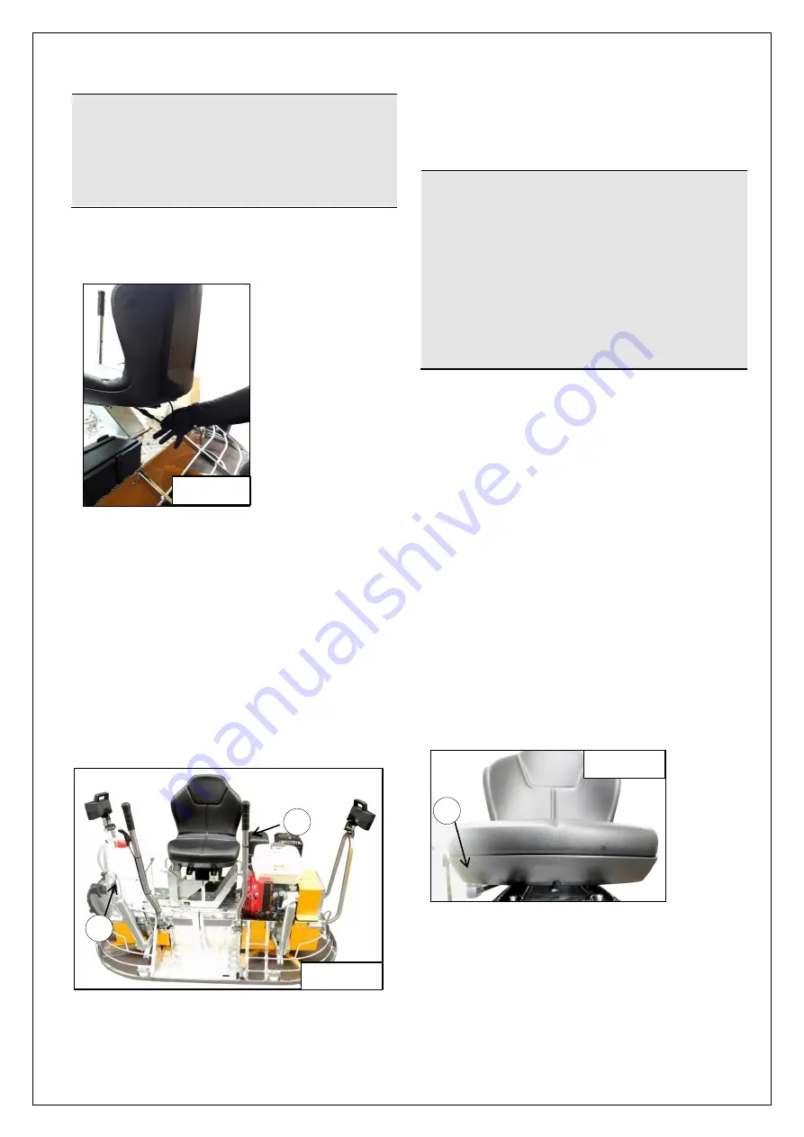
Connect the wire of the seat
microswitch (fig. 4.5).
●
Upon receipt check that the trowel
arrives intact. Otherwise contact our dealer
(see PAR. 3.5).
Water supply
The trowel is provided with a water delivery
system consisting of a tank (1, fig. 4.6)
placed on the right side of the machine.
The water supply (in some cases necessary
for processing) is carried out by pressing the
appropriate control located above the left
control lever (2, fig. 4.6).
Special sprinkling nozzles positioned at the
bottom of the machine channel water on the
working surface.
4.2
INITIAL CHECKS
1.
Check the oil level in the engine and, if
necessary, top it up (par. 4.3.4);
2.
Check the fuel level in the tank and, if
necessary, arrange its filling (par.4.3.3);
!
CAUTION
It is recommended to make sure that
the petrol contains no water and not
to
use
mixtures
or
diesel.
Perform this operation in a well
ventilated environment and away from
possible sources of heat or flames.
Make use of specific PPE (for airway
protection) as shown in the residual
risks table on page 20 of this
publication.
3.
Ensure that all guards are present,
efficient and functional;
4.
Adjust the position of the seat horizontally
in order to obtain the best possible
working position (section 4.3.);
5.
Check that the inclination degree of blades
is at least 1 cm. in order to have a greater
control of the trowel upon starting. (For the
adjustment see par. 5.4);
6.
Make sure that the trowel is placed on an
equal plane with a capacity greater than
300 kg/m
2
and that there is sufficient
space around the trowel (at least 2 m. );
7.
Check that the two control levers are
perpendicular, if necessary adjust them
(see par. 4.3.2).
4.3
PRELIMINARY STARTUP
OPERATIONS
Seat adjustment
(Fig.4.7)
For horizontal adjustment activate
the lever under the seat, find the desired
position and release the lever (1, fig. 4.6).
Figure 4.5
Figure 4.6
1
2
1
Figure 4.7
Summary of Contents for MK8-75
Page 19: ...19 of 68...
Page 20: ...20 of 68...
Page 21: ...21 of 68...
Page 22: ...22 of 68...
Page 23: ...23 of 68...
Page 38: ...38 of 68 5 5 LAYOUT OF CONTROLS...
Page 50: ...50 of 68 ATTACHED WIRING DIAGRAM...
Page 51: ...51 of 68 6 5 PARTS LIST...
Page 52: ...52 of 68...
Page 53: ...53 of 68...
Page 54: ...54 of 68...
Page 55: ...55 of 68...
Page 56: ...56 of 68...
Page 57: ...57 of 68...
Page 58: ...58 of 68...
Page 59: ...59 of 68...
Page 60: ...60 of 68...
Page 61: ...61 of 68...
Page 62: ...62 of 68...
Page 63: ...63 of 68...
Page 64: ...64 of 68...
Page 65: ...65 of 68...
Page 66: ...66 of 68...
Page 67: ...67 of 68...


