32 of 68
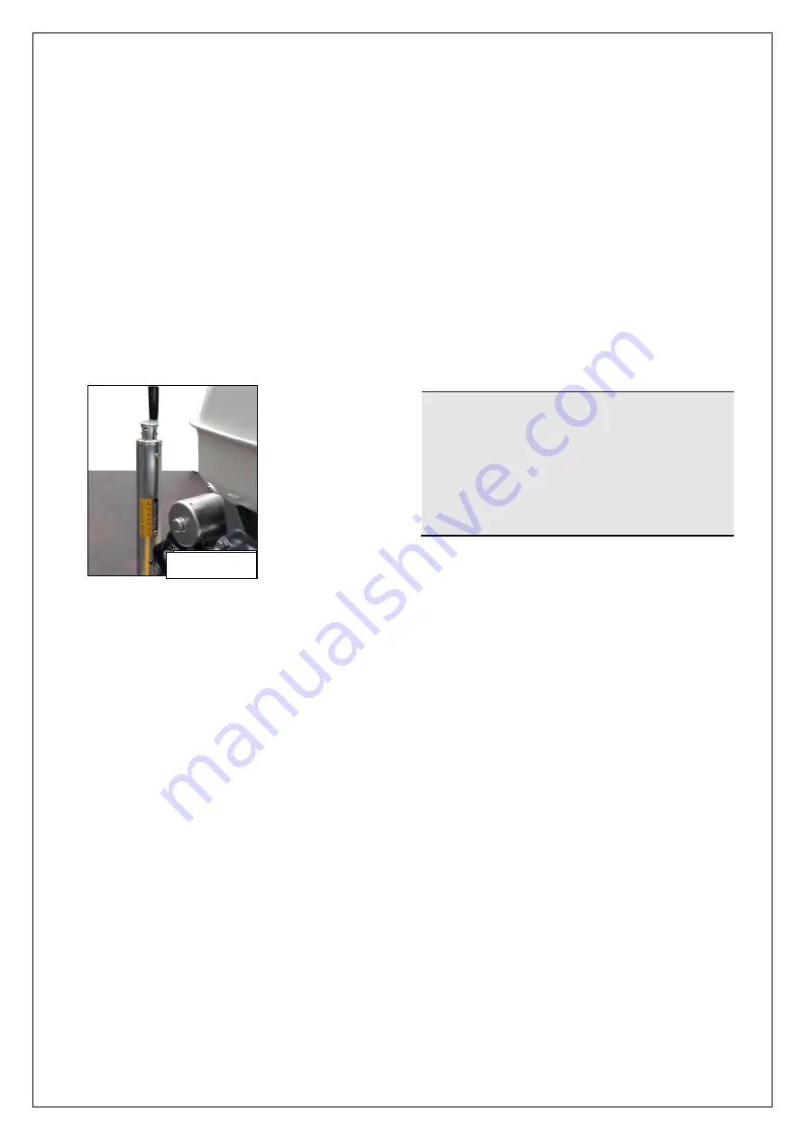
Figure 4.8
Control levers’ adjustment
The steering levers (fig. 2.1 # 6 and 7) can be
adjusted to make the driving operation easier,
adapting them to the driver needs.
The levers must remain perfectly straight in
the rest position. Wear and prolonged use
over time may alter the location and may
require adjustment.
To move the steering control levers
forward or backward the operator must:
1.
Arrange the blades in a horizontal position
by activating the appropriate levers and
adjust himself through the graduated bar
present on the tubular fig. 4.8).
2.
To perform this adjustment you need to
intervene on the internal tie-rods, after
having removed the aluminium cover lid
unscrewing the 6 fixing screws.
3.
Remove the retainer clip of the tie rod
joints;
4.
Remove the tie rod from its seat, pulling
the joint off;
5.
Adjust the tie rod end:
●
By rotating the joint in a clockwise
direction
the
levers
are
moved
outwards (FORWARD)
●
By rotating the joint counter-clockwise
the
levers
move
inwards
(BACKWARD).
6.
Reposition the joint and keep it in place by
means of the clip, repeating in reverse the
operations previously described.
7.
Finally replace the cover previously
removed.
To move the steering control levers to the
right or to the left the operator must:
1.
Remove the retainer clip of the tie rod
joints;
2.
Remove the tie rod from its seat,
pulling the joint off;
3.
Adjust the tie rod end:
●
By rotating the joint clockwise the
levers move to the left;
●
By rotating the joint counter-clockwise
the levers move to the right;
Reposition the joint and fix the clip.
Fuel filling
!
CAUTION
CAUTION
Danger of explosion and fire.
Fill the tank only in an open space,
away from heat sources. Do not
smoke. Do not refuel while the engine
is running or hot.
1.
Clean the area around the fuel cap.
2.
Remove the cap.
3.
Fill the tank up to 3-4 centimetres from
the upper edge of the tank to allow the
fuel to expand.
4.
Replace the tank cap.
5.
Always clean the area of the cap
thoroughly by removing any small leaks.
Engine oil filling
Refer to the engine manual attached and to
the MAINTENANCE CHAPTER OF THIS
PUBLICATION.
Refer to par. 6.2.5 to perform the engine oil
filling.
Figure 4.8
Summary of Contents for MK8-75
Page 19: ...19 of 68...
Page 20: ...20 of 68...
Page 21: ...21 of 68...
Page 22: ...22 of 68...
Page 23: ...23 of 68...
Page 38: ...38 of 68 5 5 LAYOUT OF CONTROLS...
Page 50: ...50 of 68 ATTACHED WIRING DIAGRAM...
Page 51: ...51 of 68 6 5 PARTS LIST...
Page 52: ...52 of 68...
Page 53: ...53 of 68...
Page 54: ...54 of 68...
Page 55: ...55 of 68...
Page 56: ...56 of 68...
Page 57: ...57 of 68...
Page 58: ...58 of 68...
Page 59: ...59 of 68...
Page 60: ...60 of 68...
Page 61: ...61 of 68...
Page 62: ...62 of 68...
Page 63: ...63 of 68...
Page 64: ...64 of 68...
Page 65: ...65 of 68...
Page 66: ...66 of 68...
Page 67: ...67 of 68...


