PCI-DAS1602/12 User's Guide
Installing the PCI-DAS1602/12
11
Configuring the PCI-DAS1602/12
All hardware configuration options on the PCI-DAS1602/12 are software controlled. You can select some of
the configuration options using
Insta
Cal, such as the analog input configuration (16 single-ended or eight
differential channels), the edge used for triggering when using an external pacer, and the counter source. Once
selected, any program that uses the Universal Library initializes the hardware according to these selections.
Connecting the board for I/O operations
Connectors, cables
– main I/O connector
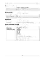
The table below lists the board connectors, applicable cables, and compatible accessory products for the PCI-
DAS1602/12.
Board connector, cables, and accessory equipment
Connector type
100-pin high-density Robinson-Nugent
Compatible cables
C100FF-x
Compatible accessory
products with the
C100FF-x cable
ISO-RACK16/P
ISO-DA02/P
BNC-16SE
BNC-16DI
CIO-MINI50
CIO-TERM100
SCB-50
SSR-RACK24 (DADP-5037 adaptor required)
SSR-RACK08 (DADP-5037 with TN-MC78M05CT adaptor required)
CIO-ERB24 (DADP-5037 adaptor required)
CIO-ERB08 (DADP-5037 adaptor required)
CIO-SERB08 (DADP-5037 adaptor required)
The PCI-DAS1602/12 board's main I/O connector is a 100-pin high density connector labeled
J1
. All signals
pass through this connector. The pinout for eight-channel differential mode is listed on page 12. The pinout for
16-channel single ended mode is listed on page 13.
Information on signal connections
General information regarding signal connection and configuration is available in the
Guide to Signal
Connections
www.mccdaq.com/signals/signals.pdf)
.
Caution!
When connecting a cable to the board's I/O connector, make sure that the arrow indicating pin 1
on the board connector lines up with the arrow indicating pin 1 on the cable connector.
Connecting cables can damage the board and the I/O controller.
Summary of Contents for PCI-DAS1602
Page 1: ......


