background image

McCauley MCS 2.6 User’s Manual

Summary of Contents for MCS 2.6

Page 1: ...McCauley MCS 2 6 User s Manual...

Page 2: ...TANT SAFETY INFORMATION DO NOT REMOVE COVERS NO USER SERVICEABLE PARTS INSIDE REFER SERVICING TO QUALI FIED SERVICE PERSONNEL THIS EQUIPMENT MUST BE GROUNDED IT SHOULD NOT BE NECESSARY TO REMOVE ANY P...

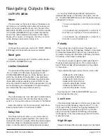
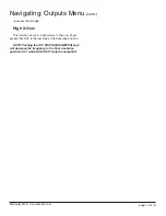
Page 3: ...ection Controls Meters Enter Key STORE Parameter Keys Last Next Up Down Keys Mute Key s Input Meter Mute Led s Output Meter Navigating Utilities Menu Stereo Link Delay Units Lock Out MIDI Channel Cont...

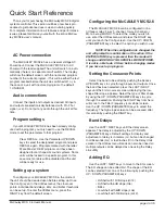
Page 4: ...ess the RIGHT key from the default screen Configuring the McCAULEY MCS2 6 The McCAULEY MCS2 6 can be configured in one of three modes 2 way 3 channel 3 way 2 channel or Mono 5 way MONO To select the m...

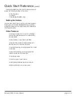
Page 5: ...threshold setting Other Features Crossover slopes of 6 12 18 24 or 48dB per octave filter types Butterworth or Linkwitz Riley as appropriate Output limiters on each band mid filter High resolution inp...

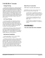
Page 6: ...x 5mm T fuse rated at 1A for continued protection from equipment damage and fire It is most important for continued safety that this specification is strictly adhered to Mechanical Installation A ver...

Page 7: ...Signal Hot Pin 3 Signal Cold 2 Channel Inputs The McCAULEY MCS2 6 audio inputs are electroni cally balanced Transformer balancing is available as a retrofit option Pin 1 Open circuit Pin 2 Signal Hot...

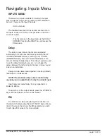
Page 8: ...The mute LED is illuminated when the output is MUTED Mute status is saved when a program is stored INPUT Meter Input signal level referenced to the clip level Actual signal clipping will occur slightl...

Page 9: ...DI ensure that both devices are set to the same MIDI channel and connect either the MIDI OUT of the Tx device to the MIDI IN of the Rx device Alternatively the units can be linked via their RS232 port...

Page 10: ...ement decrement the amount of delay in larger steps This delay is typically used to set the delay for delay towers etc or to stagger the delays between the left and right channels to move sound lobes...

Page 11: ...cabinet have been aligned the whole cabinet can be delayed relative to the input signal or another cabinet by linking these band delays as one Any offsets applied before linking will be retained after...

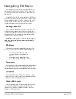
Page 12: ...rks in a similar way to the Low Xover except that OUT is the last step at the clockwise position NOTE Pushing the UP DOWN PARAMETER keys will decrease the frequency to the final clockwise position OUT...

Page 13: ...be inserted automatically NOTE The A B signal is summed after the EQ sec tions on A and B so the A B signal is affected by A and B EQ EQ Shape The shape of the EQ can be selected from one of the foll...

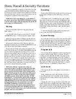
Page 14: ...rn the Lock on off the default setting being ON Once the Lock status is set push the ENTER STORE key a final time to commit the program to memory The display will now default back to the screen displa...

Page 15: ...ctronically balanced floating Input Impedance 10kW Maximum Input Level 20dBu balanced Outputs Electronically balanced floating Maximum Output Level 10dBu into 600W Channel Separation 80dB 20Hz 20kHz P...

Reviews: