18
\
AUX
AUX
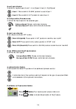
Gear Control Switch
Selects the required gear; Gear 1 = Low Speed / Gear 2 = High Speed
Gear I:
Place switch in ‘DOWN’ position to select Gear 1
Gear II:
Place switch in ‘UP’ position to select Gear 2
Gear Speed Dial (Potentiometer)
Controls the travel speed in the selected gear;
Increase Speed:
Rotate control dial clockwise
Decrease Speed:
Rotate control dial anti-clockwise
Rotor Control Switch
Rotor direction ON and OFF control;
Rotor ON (Uphill):
Place switch in ‘UP’ position to start the rotor ‘uphill’
Rotor OFF:
Place switch in the central position to ‘STOP’ rotor
Rotor ON (Downhill):
Place switch in ‘DOWN’ position to start the rotor ‘downhill’
Rotor RPM Control Dial (Potentiometer)
Controls the rotor speed;
Increase Rotor RPM:
Rotate control dial clockwise
Decrease Rotor RPM:
Rotate control dial anti-clockwise
Auxiliary Control Switch
Control switch for ON/OFF operation of an additional hydraulic service;
Control direction of the auxiliary switch will depend on the type of equipment fitted
and installation of the hydraulic connections.
Pair Button & Float Control Button
Press
\
Button:
Pair machine and remote control unit
Press
Button:
Activation/deactivation of ‘float’ feature.


