21
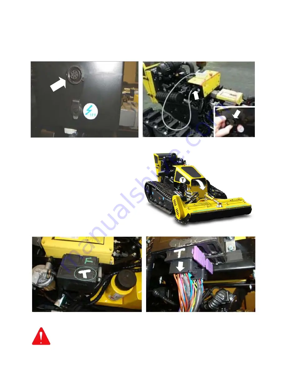
Location of Brake Control Module (T)
Converting the Machine for use with the Manual Control Unit
The method of adapting the machine for use with the manual control unit requires attachment of
the Control Unit and deactivation of the Brake Control Module; the procedures are as follows;
Control Unit Attachment
Connect the manual control unit to its connection point on the electronic ignition box, this point
is located on the right hand side of the machine as shown in the photos below.
Deactivating the Brake Control Module
Under normal operating conditions when
using the remote control, movement of the
joystick sends a signal to the brake system
instructing it to release the brakes.
When using the manual control unit the
brake controller must be bypassed to allow
the brakes to release, this is achieved by
disconnecting the wiring loom from the
brake control module.
The brake control module is located under
the bonnet on the right hand side of the
machine –
indicated ‘T’ in the photographs
opposite and below.
Note: Failure to disconnect the Brake Control Module will result in the engine
stalling when attempting to transport the machine in Manual Control Mode.
Location of connection point for the Manual Control Unit Remove dust cover and plug unit into the connection point
Brake Control Module identification (indicated ‘T’) Disconnect the wiring loom plug from the Brake Control
Module to allow machine operation with Manual Control
Summary of Contents for RoboCut
Page 7: ......
Page 47: ...40...
Page 48: ...41 ROBOCUT Parts Section...
Page 49: ...42 CHASSIS ASSEMBLY ROBOCUT McCON NEL...
Page 51: ...44 RUBBER TRACKS ROBOCUT McCON NEL...
Page 53: ...46 EQUIPMENT MOUNTING ASSEMBLY ROBOCUT McCON NEL...
Page 55: ...48 ENGINE COVER ASSEMBLY ROBOCUT McCON NEL...
Page 57: ...50 MACHINE COVER ASSEMBLY ROBOCUT McCON NEL...
Page 59: ...52 DIESEL ENGINE ASSEMBLY ROBOCUT McCON NEL...
Page 61: ...54 DIESEL ENGINE ASSEMBLY ROBOCUT McCON NEL...
Page 63: ...56 DIESEL ENGINE COMPONENTS ROBOCUT McCON NEL...
Page 65: ...58 PUMPS ASSEMBLY ROBOCUT McCON NEL...
Page 67: ...60 ACTUATOR ASSEMBLY ROBOCUT McCON NEL...
Page 69: ...62 REVERSIBLE FAN SYSTEM ROBOCUT McCON NEL...
Page 71: ...64 DIESEL FUEL CIRCUIT ROBOCUT McCON NEL...
Page 73: ...66 OIL TANK ASSEMBLY ROBOCUT McCON NEL...
Page 75: ...68 ELECTRICAL COMPONENTS ROBOCUT Machine Serial No 00088 McCON NEL...
Page 77: ...70 ELECTRICAL COMPONENTS ROBOCUT Machine Serial No 00089 McCON NEL...
Page 79: ...72 ELECTRICAL WIRING ROBOCUT McCON NEL...
Page 81: ...74 TRANSMITTING RECEIVING UNITS ROBOCUT McCON NEL...
Page 83: ...76 TRANSMITTING RECEIVING UNITS Pure Models ROBOCUT McCON NEL...
Page 85: ...78 INTAKE DRAIN PUMPS ROBOCUT Machine Serial No 00028 00088 McCON NEL...
Page 87: ...80 INTAKE DRAIN PUMPS ROBOCUT Machine Serial No 00089 McCON NEL...
Page 89: ...82 CHANGE OVER VALVE CIRCUIT ROBOCUT Machine Serial No 00073 McCON NEL...
Page 91: ...84 TRACKS HYDRAULIC CIRCUIT ROBOCUT Machine Serial No 00088 McCON NEL...
Page 93: ...86 TRACKS HYDRAULIC CIRCUIT ROBOCUT Machine Serial No 00089 McCON NEL...
Page 95: ...88 HYDRAULIC RAMS CIRCUIT ROBOCUT McCON NEL...
Page 97: ...90 HYDRAULIC EQUIPMENT CIRCUIT ROBOCUT McCON NEL...
Page 103: ...96 ROTORS FLAILS ROBOCUT McCON NEL...
Page 107: ......


