Technical specifications
247
9
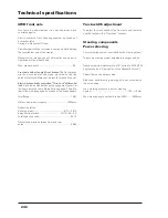
Hydraulic circuit
Two stage hydraulic gear pump powered directly by the
gears of the timing system with 40 micron double paper
filter on the intake.
The two pump stages supply:
1st Stage: delivery 29,9 l/min at a 2200 RPM engine rate.
20 micron paper filter on the delivery.
Supplies: - The power steering circuit, max. operating
pressure 150 +/- 5 bar.
- The 17-18 bar low pressure circuit including
Xtrashift, the four-wheel drive, the hydraulic
Power Take-Off, the hydraulic brake of the Po-
wer Take-Off, the differential lock and T-tronic
(if installed).
- The oil cooling circuit, max. pressure 5 bar.
- The lubricating circuit of the gearbox, max.
pressure 1.5 bar.
2nd Stage: flow rate 60 l/min at 2200 RPM engine rate. -
Supplies: - The hydraulic trailer brake, max. operating
pressure 130 +/- 10 bar.
- The auxiliary control valves (max. 4), max.
operating pressure 180 +/- 5 bar.
- The hydraulic power lift, max. operating pres-
sure 180 +/- 5 bar.
Electronically controlled power lift
Draft control, position control, “Intermix” combined draft
and position control, and float mode.
Monitoring system ...........................................Electronic
Type of control ......................................Electro-hydraulic
Electronic plant, sensors
and electro-distributor ..........................................BOSCH
Draft control by means of 2 sensors fitted to the lower
links of the three point linkage.
Operating voltage rating .......................................12 Volt
Three-point linkage
[4.2.g]
Class 2 three-point linkage with side stabilizers to limit
implement swing.
Adjuster crank on RH vertical link rod. Optional hydraulic
adjuster jack.
Adjuster crank of LH link rod with two positions at the
lower end: one fixed and the other sliding.
Lower links with quick hitch mechanisms on request.
Top link with quick hitch mechanism, optional hydraulic
adjuster jack.
Three point linkage powered by one single-acting hydrau-
lic cylinder, diameter 100 mm, coupled to two auxiliary
cylinders mounted as standard.
Max. lifting capacity at ends of articulated rods in hori-
zontal position
:
• with 2 auxiliary cylinders, diam. 60 mm (on request)
(max. pressure 200 bar) ................................5000 Kg.
Auxiliary control valves
Open center auxiliary control valves with rapid “Push-Pull”
attachments.
The auxiliary control valves use the power lift pump, thus
the max. operating pressure is 180 bar.
NOTE: Ask your Dealer for complete configurations of
auxiliary control valves.
Summary of Contents for X60 Series
Page 39: ...39 Controls Cab 3 Section 3 Controls Cab...
Page 61: ...61 Instruments and Programming 4 Section 4 Instruments and Programming...
Page 90: ...90 Instruments and Programming This page has been left blank intentionally...
Page 91: ...91 Operation 5 Section 5 Operation...
Page 151: ...149 Tyres Wheels Ballasting 6 Section 6 Tyres Wheels Ballasting...
Page 168: ...166 Tyres Wheels Ballasting This page has been left blank intentionally...
Page 169: ...167 Maintenance 7 Section 7 Maintenance...
Page 229: ...Electrical system 227 8 Section 8 Electrical system...
Page 242: ...Electrical system 240 Page left intentionally blankf...
Page 256: ...Technical specifications 254 This page has been left blank intentionally...
Page 262: ...260 Alphabetical index...

