67
Instruments and Programming
4
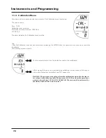
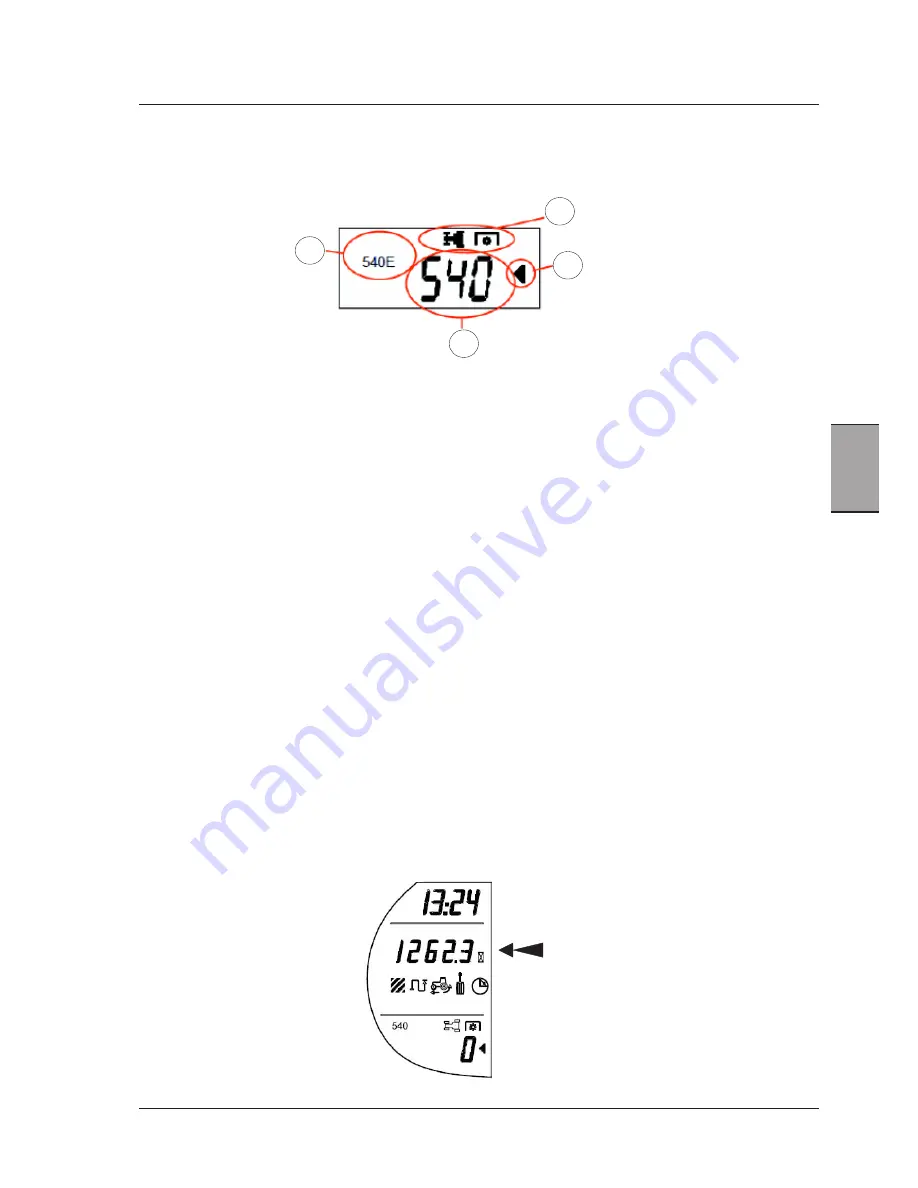
This display will be configured as follows:
1 - Rear/front PTO selected
The selected PTO display indicates that the LCD is showing whether the front or rear PTO was engaged.
The MENU button displays one of these indications.
2 - Arrow indicating the PTO/hour menu is selected.
The arrow indicates that in this moment the functions of the PTO/hours menu are selected for display.
By means of the UP and DOWN buttons the operator can scroll the different MENU options and the arrow indicates which
view has been selected.
3 - PTO instantaneous speed - RPM
Indicates the actual speed of the engaged PTO. If the PTO is not engaged, the display shows "0". If when the PTO is dis-
engaged a value different from "0" is shown, that means a dragging effect is present. Ask your Dealer's workshop for help.
4 - PTO speed selected
The “PTO speed selected” display indicates 540 or 540E or 1000 (or 1000E, if applicable) according to tractor configuration
and to the PTO speed that is selected by the speed selector lever.
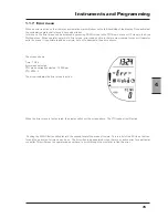
Front Pto
- Ignition key ON. The front PTO can be displayed in the lower area of the left-hand LCD (select PTO display by the up/
down arrows and press the MENU button). The display shows the front PTO speed, as calculated from engine speed rate
with gear engaged in the factory setting. If the front PTO is not active, the display reads 0. If the front PTO is engaged,
the value of the rev speed rate is shown on the LCD screen.
When the key is switched to OFF, the front PTO view is cancelled, and when the key is switched to ON, the procedure
starts again at the first start of the front PTO.
WORK HOURS
The display shows the actual hours worked by the tractor. The count is only active when the engine is running. The value
displayed ranges from 0.0 to 9999.9. When the maximum value is reached, the displayed value ranges from 10000 to
60000. When 60000 is reached, the count will stop.
Rear Power Take-Off
[4.2.d]
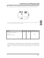
According to the PTO on board, the display will show the following:
1
2
4
3
Summary of Contents for X60 Series
Page 39: ...39 Controls Cab 3 Section 3 Controls Cab...
Page 61: ...61 Instruments and Programming 4 Section 4 Instruments and Programming...
Page 90: ...90 Instruments and Programming This page has been left blank intentionally...
Page 91: ...91 Operation 5 Section 5 Operation...
Page 151: ...149 Tyres Wheels Ballasting 6 Section 6 Tyres Wheels Ballasting...
Page 168: ...166 Tyres Wheels Ballasting This page has been left blank intentionally...
Page 169: ...167 Maintenance 7 Section 7 Maintenance...
Page 229: ...Electrical system 227 8 Section 8 Electrical system...
Page 242: ...Electrical system 240 Page left intentionally blankf...
Page 256: ...Technical specifications 254 This page has been left blank intentionally...
Page 262: ...260 Alphabetical index...


