background image

12

MAINTENANCE

MUFFLER

Do not operate tiller without muffler. Do not tamper with 

exhaust system. Damaged mufflers or spark arresters could 

create a fire hazard. Inspect pe ri odi cally and re place if 

nec es sary. If your engine is equipped with a spark arrester 

screen assembly, re move every 50 hours for cleaning and 

inspection. Re place if dam aged.

SPARK PLUG

Replace spark plugs at the beginning of each tilling sea-

 son or after every 50 hours of use, whichever comes first.  

Spark plug type and gap setting are shown in “PROD UCT 

SPEC I FI CA TIONS” on page 3 of this manual.

TRANSMISSION

Your transmission is sealed and will not require lubrication 

unless serviced.

CLEANING

Do not clean your tiller when the engine and transmission 

are hot.  We do not rec om mend using pressurized water 

(gar den hose, etc.) to clean your unit un less the gasket 

area around the trans mis sion and the engine muf fler, air 

fil ter and car bu re tor are cov ered to keep wa ter out.  Wa ter 

in en gine will short en the useful life of your tiller. 
•  Clean engine, wheels, finish, etc. of all foreign mat-

ter.

• 

Keep finished surfaces and wheels free of all gas o line, 

oil, etc.

•  Protect painted surfaces with au to mo tive type wax.

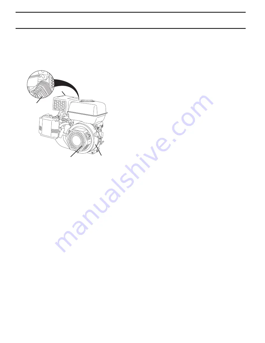
Fig. 14

COOLING SYSTEM


(See Fig. 14)

Your engine is air cooled.  For proper en gine performance 

and long life keep your engine clean.

• 

Clean air screen  frequently using a stiff-bristled brush.

•  Remove blower housing and clean as nec es sary.
•  Keep cylinder fins free of dirt and chaff.

Cylinder Fins

Muffler

Air Screen

Blower 

Housing

Summary of Contents for 532 43 21-09

Page 1: ...532 43 21 09 MC900 Operator s Manual 96083000400 2009 11...

Page 2: ...ever allow adults to operate the equipment without proper instruction Keep the area of operation clear of all persons par ticularly small children and pets PREPARATION Thoroughly inspect the area wher...

Page 3: ...EETING APPLICABLE LOCAL LAWS IF ANY IFASPARKARRESTERISUSED ITSHOULDBEMAINTAINED IN EFFECTIVE WORKING ORDER BY THE OPERATOR IN THE STATE OF CALIFORNIA A SPARK ARRESTER IS REQUIRED BY LAW SECTION 4442 O...

Page 4: ...n of your tiller all parts and hardware you assemble must be tightened securely Use the correct tools as necessary to insure proper tightness TOOLS REQUIRED FOR ASSEMBLY A socket wrench set will make...

Page 5: ...h_stake_4 DEPTH STAKE SUPPORT BOLT HEX BOLTS LOCK WASHERS AND HEX NUTS DEPTH STAKE SUPPORT NUT A ENGINE BRACKET HALVES Fig 3 STAKE SPRING ASSEMBLY HANDLE HEIGHT Handle height may be adjusted to better...

Page 6: ...rds of the American National Standards Institute OPERATION CHOKE CONTROL Used when starting a cold engine DEPTH STAKE Controls forward speed and the depth at which tiller will dig ENGINE ON OFF SWITCH...

Page 7: ...Fig 6 Adjust depth stake by removing the hairpin clip and clevis pin Change depth stake to desired position Replace the clevis pin and hairpin clip For normal tilling set depth stake at the second or...

Page 8: ...flame IMPORTANT WHEN OPERATING IN TEMPERATURES BELOW32 F 0 C USE FRESH CLEAN WINTER GRADE GASOLINE TO HELP INSURE GOOD COLD WEATHER STARTING CAUTION Alcohol blended fuels called gasohol or using etha...

Page 9: ...the soil Soilconditionsareimportantforpropertilling Tineswill notreadilypenetratedry hardsoilwhichmaycontribute to excessive bounce and difficult handling of your tiller Hard soil should be moistened...

Page 10: ...CONTROL c IDLER ARM GENERAL RECOMMENDATIONS The warranty on this tiller does not cover items that have beensubjectedtooperatorabuseornegligence Toreceive fullvaluefromthewarranty theoperatormustmainta...

Page 11: ...ou check the oil level TO CHANGE ENGINE OIL See Figs 11 and 12 Determine temperature range expected before oil change All oil must meet API service classification SG SL Be sure tiller is on level surf...

Page 12: ...erviced CLEANING Do not clean your tiller when the engine and transmission are hot We do not recommend using pressurized water garden hose etc to clean your unit unless the gasket area around the tran...

Page 13: ...Fig 16 Assemble holes A in tine hubs to holes B in tine shaft Fig 18 NARROW TILLING CULTIVATING 12 3 4 PATH See Fig 18 Remove outer tines tine_6 INNER TINES ONLY NOTE When reassembling outer tines be...

Page 14: ...e belt guard by reversing above procedure Be sure slot in bottom of belt guard is under head of tine shield bolt and all nuts are tightened securely TO REPLACE V BELT See Fig 21 Replace V belt if it h...

Page 15: ...eplace belts if necessary See belt re placement instructions in the Service and Adjustments section of this manual Lubricate as shown in the Maintenance section of this manual Be sure that all nuts bo...

Page 16: ...6 Stale or dirty fuel 6 Empty fuel tank and refill with fresh gasoline 7 Water in fuel 7 Empty fuel tank and carburetor and refill tank with fresh gasoline 8 Clogged fuel tank 8 Remove fuel tank and...

Page 17: ...17 SERVICE NOTES...

Page 18: ...18 SERVICE NOTES...

Page 19: ...19 SERVICE NOTES...

Page 20: ...his Warranty does not apply to any product which has been subjected to alteration misuse abuse improper assembly or installation delivery damage or to normal wear of the product 5 Exclusions Excluded...

Reviews: