background image

12

13

5 - OPERATING INSTRUCTIONS 

5-3. RE-STARTING A WARM ENGINE

1. Make sure the on/off switch is in the “I” position.

2. Depress the primer bulb 10 times.

3. Set the throttle latch. Latch throttle advance: depress

latch and hold squeeze throttle trigger release trigger
and then the latch.

4. Pull the starter rope rapidly 4 times. The engine

should start.

5. Release the throttle latch. The throttle latch will be

released while you press the trigger.

6. If the engine still can not start, follow the step as “To

start engine” section in this user manual.

5-4. TO STOP ENGINE

1. Release trigger and allow engine to return to idle

speed.

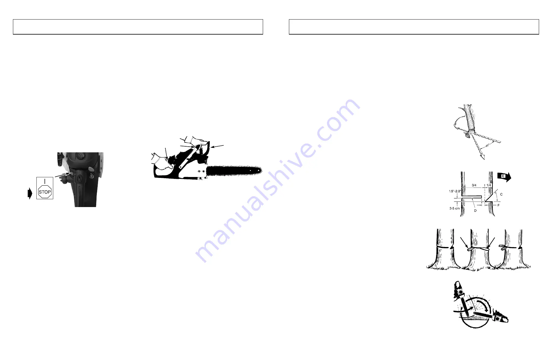
2. Press STOP switch down to stop engine Figure 5-4A.

NOTE:

For emergency stopping, simply activate CHAIN

BRAKE

®

and move STOP switch down.

INERTIA CHAIN BRAKE

®

ACTION :

NOTE:

THIS SAW IS EQUIPPED WITH AN INERTIA

CHAIN BRAKE.IF THE SAW KICKS BACK WHILE IN
USE, THE INERTIA OF THE MOVING SAW WILL ACTI-
VATE THE BRAKE. A BRAKE BAND AROUND THE
CLUTCH DRUM ACTIVATES AND STOPS THE MOVING
CHAIN.

5-5.CHAIN BRAKE

®

OPERATIONAL TEST

Test the CHAIN BRAKE

®

periodically to ensure proper

function.
Perform a CHAIN BRAKE

®

test prior to initial cutting, fol-

lowing extensive cutting, and definitely following any
CHAIN BRAKE

®

service.

TEST CHAIN BRAKE

®

AS FOLLOWS:

1. Place saw on a clear, firm, flat surface.
2. Start engine.
3. Grasp the rear handle (A) with your right hand (Figure

5-5A).

4. With your left hand, hold the front handle (B) [not

CHAIN BRAKE

®

lever (C)] firmly (Figure 5-5A).

5. Squeeze the throttle trigger to 1/3 throttle, then imme-

diately activate the CHAIN BRAKE

®

lever (C) (Figure

5-5A).

WARNING

Activate the CHAIN BRAKE

®

slowly and deliberately. Keep

the chain from touching anything; don’t let the saw tip for-
ward.
6. Chain should stop abruptly. When it does, immediately

release the throttle trigger.

WARNING

If chain does not stop, turn engine off and take your unit
to the nearest Authorized Service Center for service.
7. If CHAIN BRAKE

®

functions properly, turn the engine

off and return the CHAIN BRAKE

®

to the DISEN-

GAGED position.

5-6.SAW CHAIN / BAR LUBRICATION

Adequate lubrication of the saw chain is essential at all
times to minimize friction with the guide bar.
Never starve the bar and chain of oil. Running the saw
with too little oil will decrease cutting efficiency, shorten
saw chain life, cause rapid dulling of chain, and cause
excessive wear of bar from overheating. Too little oil is evi-
denced by smoke, bar discoloration or pitch build-up.

NOTE:

Saw chain stretches during use, particularly when

it is new, and it will occasionally be necessary to adjust
and tighten it. New chain will require adjustment after
about 5 minutes of operation.

5-7.AUTOMATIC OILER

Your chain saw is equipped with an automatic clutch driv-
en oiler system. The oiler automatically delivers the proper
amount of oil to the bar and chain. As the engine speed
increases, so does the oil flow to the bar pad. There is no
flow adjustment. The oil reservoir will run out at approxi-
mately the same time as the fuel supply runs out.

5-4A

5-5A

A

C

B

6 - GENERAL CUTTING INSTRUCTIONS

6-1.FELLING

Felling is the term for cutting down a tree. Small trees up to
6-7 inches (15-18cm) in diameter are usually cut in a single
cut. Larger trees require notch cuts. Notch cuts determine
the direction the tree will fall.

FELLING A TREE:

WARNING

A retreat path (A) should be planned and cleared as nec-
essary before cuts are started. The retreat path should
extend back and diagonally to the rear of the expected line
of fall, as illustrated in Figure 6-1A.

CAUTION

If felling a tree on sloping ground, the chain saw operator
should keep on the uphill side of the terrain, as the tree is
likely to roll or slide downhill after it is felled.

NOTE:

Direction of fall (B) is controlled by the notching cut.

Before any cuts are made, consider the location of larger
branches and natural lean of the tree to determine the way
the tree will fall.

WARNING

Do not cut down a tree during high or changing winds or if
there is a danger to property. Consult a tree professional.
Do not cut down a tree if there is a danger of striking utility
wires; notify the utility company before making any cuts.

GENERAL GUIDELINES FOR FELLING
TREES:

Normally felling consists of 2 main cutting operations,
notching (C) and making the felling cut (D).
Start making the upper notch cut (C) on the side of the tree
facing the felling direction (E). Be sure you don t make the
lower cut too deep into the trunk.
The notch (C) should be deep enough to create a hinge (F)
of sufficient width and strength. The notch should be wide
enough to direct the fall of the tree for as long as possible.

WARNING

Never walk in front of a tree that has been notched.
Make the felling cut (D) from the other side of the tree and
1.5 - 2.0 inches (3-5 cm) above the edge of the notch (C)
(Figure 6-1B).
Never saw completely through the trunk. Always leave a
hinge. The hinge guides the tree. If the trunk is completely
cut through, control over the felling direction is lost.
Insert a wedge or felling lever in the cut well before the tree
becomes unstable and starts to move. This will prevent the
guide bar from binding in the felling cut if you have mis-
judged the falling direction. Make sure no bystanders have
entered the range of the falling tree before you push it over.

WARNING

Before making the final cut, always recheck the area for
bystanders, animals or obstacles.

FELLING CUT:

1. Use wooden or plastic wedges (G) to prevent binding

the bar or chain (H) in the cut. Wedges also control
felling (Figure 6-1C).

2. When diameter of wood being cut is greater than the

bar length, make 2 cuts as shown (Figure 6-1D).

WARNING

As the felling cut gets close to the hinge, the tree should
begin to fall. When tree begins to fall, remove saw from cut,
stop engine, put chain saw down, and leave area along
retreat path (Figure 6-1A).

6-1D

6-1A

A

B

6-1B

6-1C

G

H


Summary of Contents for 9096311037

Page 1: ...perate your chain saw Improper use can cause serious injury This product has been tested at a computed kickback angle CKA and conforms to ANSI B175 1 2000 Annex C CAN CSA Z62 1 03 USER MANUAL Gasoline...

Page 2: ...ing Using a Sawhorse 7 MAINTENANCE INSTRUCTIONS 15 7 1 Preventive Maintenance 7 2 Air Filter 7 3 Fuel Filter 7 4 Spark Arrester Screen 7 5 Spark Plug 7 6 Carburetor Adjustment 7 7 Storing a Chain Saw...

Page 3: ...r cutting plastic masonry or non building materials 21 Do not attempt to add fuel or lubricating oil to saw while engine is running SAFETY PRECAUTIONS FOR CHAIN SAW USERS ANSI B175 1 2000 Annex C CAN...

Page 4: ...behind clutch drum G until the guide bar stops Figure 3 3E THE PUSH PINCH KICKBACK AND PULL REACTIONS Figure 2 4B A Pull B Solid objects C Push KICKBACK may occur when the NOSE or TIP of the guide bar...

Page 5: ...is difficult to rotate on guide bar or if it binds too much tension has been applied This requires minor adjustment as follows A Loosen the bar retaining nuts so it is finger tight Decrease tension b...

Page 6: ...tank A with correct fuel mixture Figure 5 1A 2 Fill the oil tank B with correct chain and bar oil Figure 5 1A 3 Be certain the CHAIN BRAKE is disengaged C before starting unit Figure 5 1A NOTE See pa...

Page 7: ...ain As the engine speed increases so does the oil flow to the bar pad There is no flow adjustment The oil reservoir will run out at approxi mately the same time as the fuel supply runs out 5 4A 5 5A A...

Page 8: ...3C NOTE The best way to hold a log while bucking is to use a sawhorse When this is not possible the log should be raised and supported by the limb stumps or by using sup porting logs Be sure the log...

Page 9: ...INSTRUCTIONS 7 4B A B C D 7 2A 7 2B B 7 3A B A C 7 2C 7 2D B E F D F 7 3A A B 7 5 SPARK PLUG NOTE For efficient operation of saw engine spark plug must be kept clean and properly gapped 1 Push STOP sw...

Page 10: ...hould always be cleaned every time saw chain is removed OIL PASSAGES Oil passages on the bar should be cleaned to ensure proper lubrication of the bar and chain during operation NOTE The condition of...

Page 11: ...f the warranty The above mentioned parties are hereinafter referred to as User 4 WHAT IS COVERED UNDER THIS WARRANTY Any failure that occurs within the applicable duration of the warranty period that...

Page 12: ...Rebonds Conseils Suppl mentaires 2 5 Etiquetas de Seguridad por Contragolpe 2 6 Symboles Internationaux 3 INSTRUCTIONS POUR MONTAGE 29 3 1 Outils pour Montage 3 2 Montage d El ments 3 3 Guide Cha ne...

Page 13: ...e moteur transporter la tron on neuse par sa poign e avant le guide cha ne et cha ne dirig s vers l arri re et le silencieux l oppos de votre corps 10 NE JAMAIS se servir d une tron onneuse endom mag...

Page 14: ...ampeurs pour un usage g n ral tel que nettoyage lagage coupe de bois br ler etc Ils ne sont pas destin s une utilisation prolong e Si l utilisation pr vue implique une mise en oeuvre de longue dur e l...

Page 15: ...age C en le tirant de fa on rec tiligne il faut un peu forcer Figure 3 3C 3 A l aide d un tournevis ou de la cl fournie dans le kit de l utilisateur ou dans la moiti sup rieure de la bo te de transpor...

Page 16: ...lons d entrainement dans la rainure D du guide cha ne Figure 3 3G REMARQUE La cha ne de la tron onneuse risque de pendre l g rement sur la partie inf rieure du guide cha ne Ceci est normal 4 Tirez la...

Page 17: ...gure 5 2H REMARQUE Si la cha ne tourne durant l immobilisation retournez la vis vers la gauche jusqu la cha ne s arr te et que l unit continue s immobiliser 5 1A C A B 5 2A 5 2B A 5 2C B 5 2D 5 2E C D...

Page 18: ...FONCTIONNEMENT 5 3 REDEMARRAGE D UN MOTEUR CHAUD 1 V rifiez que l interrupteur marche arr t est bien sur la position I 2 D pressez 10 fois la premi re ampoule 3 R gler le verrou d acc l ration Enclen...

Page 19: ...support sur toute sa longueur Il peut tre tron onn partir du dessus Eviter de plonger le guide cha ne dans la terre Figure 6 3A 2 Tron onnage d un tronc support une extr mit Effectuer d abord une cou...

Page 20: ...e r servoir carburant d un m lange huile essence appropri Voir la section Carburant et Lubrification 7 ENTRETIEN 7 5A H G 7 7A 38 7 2 FILTRE A AIR ATTENTION Ne jamais utiliser la tron onneuse sans fil...

Page 21: ...d arr t STOP vers le bas REMARQUE Il n est pas n cessaire de retirer la cha ne pour lubrifier la roulette La lubrification peut se faire sur le site du travail 2 Nettoyer la roulette du guide cha ne...

Page 22: ...gations Les parties sus mentionn es sont ci apr s d sign es sous le nom de Utilisateur 4 CE QUI EST COUVERT PAR CETTE GARANTIE Toute d faillance survenant pendant la p riode de garantie applicable et...

Page 23: ...olos Internacionales 3 INSTRUCCIONES DE ENSAMBLADO 51 3 1 Herramientas Para el Ensamblado 3 2 Requerimientos para el Ensamblado 3 3 Barra Gu a Cadena de Sierra Instalaci n de la Cubierta del Embrague...

Page 24: ...iones en las personas al usarla 1 Con una comprensi n b sica del contragolpe usted puede reducir o eliminar el elemento de sorpresa La sorpresa repentina contribuye a los accidentes 2 Mantenga un agar...

Page 25: ...do se acciona el interruptor del sistema de control de encendido apagado Nunca ajuste la barra de gu a o la cadena de la sier ra cuando el motor est funcionando 10 Tenga cuidado con las intoxicaciones...

Page 26: ...olina con gasolina debidamente mezcla da con aceite de dos tiempos y debe tambi n llenar el tenque de aceite con aceite lubricante para cadena todo esto antes de pretender encender su motosierra ADVER...

Page 27: ...aplicada Esto requiere un aj ste menor como sigue 3 INSTRUCCIONES DE ENSEMBLADO 3 3F 3 3G A D B C 3 4A D A Afloje las tuercas de sujeci n de la barra hasta que pueda hacerlo con la mano Reduzca la ten...

Page 28: ...sierra a menos que la barra y cadena se encuentrer adecuadamente instaladas 1 Rellene el dep sito de combustible A con la mezcla de combustible correcta figura 5 1A 2 Rellene el dep sito de aceite B c...

Page 29: ...forma autom tica la cantidad de aceite ade cuada a la barra y a la cadena A medida que aumenta la velocidad del motor aumenta el flujo de aceite hacia el tamp n de la cadena No existe un ajuste del f...

Page 30: ...era de sostener un tronco mientras es le ado es usar un caballete de le ado Cuando esto no es posible el tronco deber ser levantado y soportado por las ramas soporte o usando troncos de soporte Aseg r...

Page 31: ...escape en el cilin dro Ajuste firmemente 7 INSTRUCCIONES DE MANTENIMIENTO 7 4B A B C D 7 2A 7 2B B 7 3A B A C 7 2C 7 2D B E F D F 7 3A A B 7 5 BUJIA NOTA Para una operaci n eficiente del motor de la s...

Page 32: ...rra manifiesta suciedad Los rieles deben de ser limpiados cada vez que la cadena es removida PASAJES DE ACEITE Los pasajes de aceite sobre la barra deben de ser limpiados para asegurar una lubri caci...

Page 33: ...establecidos en la garant a o que seg n la ley del estado pueda obligar al emisor de la garant a a aplicarla Las partes arriba mencionadas se denominar n a partir de ahora como el Usuario 4 MBITO DE A...

Page 34: ...NO WHEN ORDERING PARTS 35cc Gas Chain Saw MODEL NO MCC1435A SERVICE SPARE PARTS LIST 22 23 22A 59B 59C 59D 59E 59A 54A 53 54 64 65 97 64A SERVICE SPARE PARTS LIST 22 23 22A 59B 59C 59D 59E 59A 54A 53...

Page 35: ...191 310802 SCREW 2 110 19 9010 311002 WIRE 1 110 20 9NCC 05U NUT 2 110 21 9SKKB 05 14 SCREW 2 110 22A AO9014 310810 US888 KIT SPARK ARRESTOR INCL 22 AND 23 110 22 9014 310810 COVER MESH 1 110 23 9016...

Page 36: ...0 54 9200 311201 DRUM ASS Y 1 110 54A AO9200 311001 US888 CLUTCH DRUM ASS Y INCL 53 AND 54 1 110 55 9014 310807 WASHER 1 110 56 9228 311004 CLUTCH ASS Y 1 110 57 9013 311002 RUBBER PLUG 1 110 59 9228...

Page 37: ...R 1 110 83 9228 310820 FUEL CAP ASS Y 1 110 84 9228 311003 HANDLE ASS Y R 1 110 85 9142 310002 PRIMER 1 110 86A AO9129 311001 US888 KIT FUEL HOSE AND FILTER 86 86B 86C AND 86D 1 110 86B 9129 311001 FU...

Reviews: