48
NON-SCHEDULED MAINTENANCE
WARNING: INSPECTION, TESTING,
AND REPAIR OF ELECTRICAL EQUIPMENT
SHOULD
ONLY
BE
PERFORMED
BY
QUALIFIED SERVICE PERSONNEL.
ALL
ELECTRICAL
CONNECTIONS
SHOULD BE DISCONNECTED AND THE
HOOD CIRCUIT BREAKER SHOULD BE
TURNED OFF WHEN SERVICING THE GRILL.
FAILURE TO DO SO MAY RESULT IN
EQUIPMENT
DAMAGE
OR
PERSONAL
INJURY.
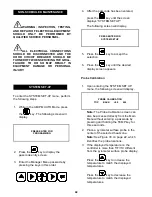
SYSTEM SET-UP
To enter the SYSTEM SET-UP menu, perform
the following steps.
1.
While in the AM/PM AUTO Mode, press
the
key. The following screen will
display.
PRESS ENTER FOR
PROGRAMMING
2.
Press the
key to display the
passcode entry screen.
3.
Enter the Manager Menu passcode by
pressing the keys in this order:
4.
After the passcode has been entered,
press the
key until the screen
displays “SYSTEM SETUP.”
The following screen will display.
PRESS ENTER FOR
SYSTEM SETUP
5.
Press the
key to accept the
selection.
6.
Press the
key until the desired
display screen appears.
Probe Calibration
1.
Upon entering the SYSTEM SET UP
menu, the following screen will display.
PROBE CALIBRATION
TOP
BACK
+00
424
Note:
The Probe Calibration screen can
also be accessed directly from the Main
Menu without entering a passcode by
pressing and holding the TEMP key for
three seconds.
2.
Place a pyrometer surface probe in the
center of the selected heat zone.
Note:
See Figure 30 on page 22, which
identifies the probe locations.
3.
If the displayed temperature on the
controller is more than 5°F/3°C different
from the pyrometer surface probe display:
Press the
key to increase the
temperature to match the displayed
temperatures.
Press the
key to decrease the
temperature to match the displayed
temperatures.
Summary of Contents for C836
Page 2: ......
Page 7: ...5 150209 C836 Exploded View Figure 1 2015 Carrier Commercial Refrigeration Inc ...
Page 9: ...7 150209 C838 Exploded View Figure 2 2015 Carrier Commercial Refrigeration Inc ...
Page 64: ...Rev 2 15 C836 C838 WIRING DIAGRAM 083305 75 ...
Page 65: ......
Page 66: ......
Page 67: ......
Page 68: ...073530 M ...

