2 - 4
Overview
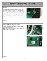
Hydraulic Manifold Block
Mounted on this block are a carriage directional control valve, a
pressure reducing selector valve, three pressure reducing valves,
and a 3000 psi gauge.
A) The carriage control valve, mounted on the top of the manifold,
determines whether the carriage is moving left, right, or is in
neutral.
B) A 3000 psi gauge is mounted on top of the manifold.
C) The selector valve, mounted on the front of the manifold, selects
a reduced pressure from one of the pressure reducing valves.
Each pressure reducing valve is labeled with a different function:
D) The top valve adjusts facing pressure to a maximum of 400 psi.
E) The middle valve adjusts heating pressure to a maximum of
400 psi.
F) The bottom valve adjusts fusion pressure to a maximum of 2300
psi, which is the set system pressure.
G) DataLogger port
TX04541-10-24-12
PH
04
731-10
-1-12
CD0013
8H-1-12
-11
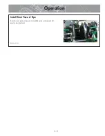
Facer
The facer is a McElroy rotating planer-block design. The blade
holders each contain three cutter blades. The block rotates on ball
bearings and is chain driven (enclosed in lubricant) by a hydraulic
motor. The facer is removable for in-ditch operation and features a
lifting point for lifting the facer in and out of the ditch.
NOTICE:
Never extend the blade beyond the inner or outer
circumference of the facer.
TX04473-10-24-12
Inlet Fans
Inlet fans are used to draw cooler air from the outside of the
machine to the generator compartment.
NOTICE:
Never obstruct the fans. Allow enough area for air to
circulate into the machine. Restricting air to the fans could cause
components to overheat and fail.
TX04990-04-27-16
PH
04
741-10
-8-12
PH
05
50
7-
04
-2
7-16


