background image

Summary of Contents for Onan GenSet 3.ORDJA

Page 1: ...BX i v 1 S ORbyA DIBSBL r l Wxr iaEylp6fei penerEtG rs r VEor T r u c k s k S r tb R ji Mount ONi Y Re3d Throu gh Entire InstaHa tion Guide j PiiMft A aklhstalJation 97 0625 t n o irt u S A ...

Page 2: ... of electricity and should be removed when working on electrical equipment DO NOT PLUG MOBILE PORTABLE OR STANDBY SETS DIRECTLY INTO A HOUSE RECEPTACLE TO PROVIDE EMERGENCY POWER It is possible for current t o flow from generator into the utility line This creates ex treme hazards to anyone working on lines to res tore power Use extreme caution when working on electrical components High voltages c...

Page 3: ...o i u t 1 i in if I ...

Page 4: ...on Instructions Specifications 5 Compartment DISASSEMBLY 6 Compartment and GenSet Installation Over The Rail Mount COOLING SYSTEM 1 1 Exhaust System Fuel System 15 Electrical Loads and Connections 1 8 Remote Starting Panel Installation 22 Connecting GenSet To Truck Batteries 25 ...

Page 5: ...ry completely assembled within the insulated compartment housing for pro tection during shipping Some housing panels and internal compartment wiring require disassembly prior to installing the generator set i n place over the truck frame rails WARNING ONAN R E C O M M E N D S T H A T G E N E R A T O R S E T INSTALLATION AND ALL S E R V I C E ONLY BE DONE BY PERSONS QUALIFIED TO PERFORM E L E C T R...

Page 6: ...g location alono thetruck frame rail will vary between different fwe itiena4 truck makes and models In cafl v rei tfi e T9P t tr ucks for Over the Rail installations a location as 4 6t w pd Sw a i back wall of truck cab is most suitable for purposes of better axle weight distribution See F i g u r e 2 Distance X listed in Table 1 when measuring for installation MUST be maintained to allow for any ...

Page 7: ...ust r e s t on t r u c k f r a m e r a i l s when i n s t a l l e d as shown i n F i g u r e 3 components such as batteries tanks or tool boxes or any other truck accessories all work must be performed by an experienced truck dealer or service person only These conditions must be identified prior to performing any part ol the auxiliary generator set installation The completed installation must con...

Page 8: ...y Ground C V f ffVn P b firfJj Negative Ground Standard Starting System c Motorized Alternator Cranking Cranking Current 300 Amperes Break away Current Maximum 4 75 Amperes Fuel Diesel demote Kael Tank G jTpacity rv y T K G llonsi J L rengt fi 2 V F 1 9mm 4 V j r u V 7 V l 5 feo i n 393nAi in Ci Qsim e th rv V r o 7 Fuel Pump Mechanical Fuel Return and Supply line Connection Size SAE 4 370 Flare N...

Page 9: ... terior of the rear back housing panel which secure the compartment fan assembly to the rear back panel as shown in Figure 4 These two boIts are 5 7 8 inches in to center from left rear corner o the compartment y y 5 Unplug the fan assembly AC cord and the water solenoid AC cord from the duplex receptacle on top of the generator end of the set inside the ho using 6 Remove the three 3 8 16 x 3 4 in...

Page 10: ...a c l e i n t e r n a l wiring or r the external cover and gasket i n s t a l l e d m t o c o e j j i p top center of r i g h t side housing panel k Z d jflMsg A p Yop iM NOTE Removal of rear back panel is NOT J i jT 1 cv 11 required f o r i n s t a l l a t i o n of the generator S ed hon f set taet lvf x r x 560 bp ...

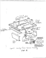
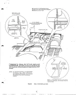
Page 11: ...each mounting clamp T o t a l t h i c k n e s s Choose any two of ten possible pairs of p r e d r i l l e d mounting holes per side that do NOT i n t e r f e r e w i t h any e x i s t ing chassis hardware frame cross mem bers or any other chassis components underneath baseplatgV of spacers used must match truck frame r a i l flange thickness under each of the four mounting clamps Use the same comb...

Page 12: ...ceed as M 1 follows 1 COMPARTMENT ASSEMBLY on each side of truck 4 mounting clamps total 2 3 The humber of spacers used w i l l vary depending upon the thickness of the truck frame r a i l s 1 Do NOT exceed the 3 4 inch maximum sp acer thickness for each clamp See Figure 4 and detail A NOTE The longer right front housing bolt 3 8 46 x 1 3 4 inches and hardware i s l e f t 4 Remove housing mounting...

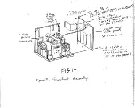
Page 13: ...trol panel and through the rear panel of compartment housing as outlined i n the Electrical Loads and Connections Section Replace the right hand side panel of the compartment housing by installing _ tsre5 3 8 l6 x 3 4 inch hex head capscrews i n e 40 ro te33 secure panel to the mounting tray See _Figure 7 Torque a l l 3 8 inch capscrews at 25 foot jounds 34N M Install the four 5 16 I8 x 3 4 inch h...

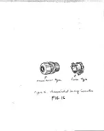
Page 14: ... a i n r e l i e f connector m nass hole out do not tighten yet Remove selected knockouts i n rear back panel and i n s t a l l o r l 2 inch water t i g h t s t r a i n r e l i e f connectors as r e quired to eaT wiring and cables but dc not tighten yet 7 _ ...

Page 15: ... a l l or truck cab compartment Use Romex connectors asfowL i n t e r i o r w i r i n g s t h r o h cab w a l l p a r t i t i o n s panels or shelves LOAD CIRC I RECOMMEN Onan recommends using conductor type SO neoprene jacke te d muTtr strand wire rated at 600 volts AC 90o C ooeration for all 20 amp circuits such as sleeper cab air conditioners Most other truck chassis starting aids such as lube ...

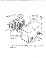
Page 16: ... which allows the driver to start the generator set from within the cab area of the truck The panel contains start stop and preheat rocker switches running time meter buzzer alarm and one AC duplex receptacle Cffl C d A k i I _ _ II 1 I J 4U 0 1 be Ofctd U VMTC ...

Page 17: ...renced in the beginning of the Electrical Loads and Connections section This kit Includes all necessary wiring and hard ware to Interconnect the remote starling panel with duplex receptacle to the generator set control panel Step by step Installation Instructions provided with each kit FJ K C A U T I O N Do NOT use so d wire or wire smaller than 16 gauge in size Solid wire will fatigue due to vibr...

Page 18: ...l and inside h e generator set control panel Ring iWpe terminals should be used to connect qpmote cable to terminal blocks inside both controls Route the D C control cable along the i n 3 side of the truck frame r a i l s where possible Secure cable every 18 inches along the run vith insulated hold down clamps closer tooeffher in bends or near high heat sources Us nylon tie wraps as required in be...

Page 19: ...COLOR CODE GENSET Terminal No L i V j r o u n d White 2 StSc Red 3 Start Green 4 Remote Alarm Signal Orange 5 D i e s e l Preheat Blue 6 X 4 Running Time Meter and Switch SI Integral Running Light VJIack 15 FOOT 3 CONDUCTOR 14 GAUGE TYPE SO AC CABLE FIGURE REMOTE STARTING PANEL INSTALLATU 73 ...

Page 20: ... I U InstaBlatioii Guide 3 0RDJA P BSEL MM GenSet AuxHjary Power Generators For Tmcks Over Tlie Rail rvlount i Cr IMPORTANT Read Through Entire Installation Guide Prior To Actual Installation 974 0625 4 82 r ftmeo in U S A ...

Page 21: ...equipment Jewelry is a good conductor of electricity and should be removed when working on electrical equipment DO NOT PLUG MOBILE PORTABLE OR STANDBY SETS DIRECTLY INTO A HOUSE RECEPTACLE TO PROVIDE EMERGENCY POWER It is possible for current to flow from generator into the utility line This creates ex treme hazards to anyone working on lines to res tore power Use extreme caution when working on e...

Page 22: ...h o 1 LA E ...

Page 23: ...ctions 5 Specifications 5 Compartment DISASSEMBLY 6 Compartment and GenSet Installation Over The Rail Mount 7 COOLING SYSTEM 1 1 Exhaust System 14 Fuel System 15 Electrical Loads and Connections 18 Remote Starting Panel Installation 22 Connecting GenSet To Truck Batteries 25 r I OVER THE RAIL INSTALLATION ...

Page 24: ...ocally prior to starting the actual installation This generator set i s shipped from the factory completely assembled within the insulated compartment housing for pro tection during shipping Some housing panels and internal compartment wiring require disassembly prior to installing the generator set i n place over the truck frame r a i l s WARNING ONAN RECOMMENDS THAT GENERATOR S E T INSTALLATION ...

Page 25: ...mounting location along thetruck frame rail will vary between different ewe 4 fl l truck makes and models C o Jj j ci_fVi 4 a b e l f c S f eyJ CWA kin ySL j4o_Cr 1tv 5 i A In cab over engine type trucks forJ Over the Rail installations a location a s 4 il Cdwacd back wall of truck cab is most suitable for purposes of better axle weight distribution See FlguxeCj Distance X listed in Table 1 when m...

Page 26: ...4 inches is NOT reduced Housing baseplate must rest on truck frame rails when installed as shown in Figure 3 modify any major truck chassis components such as batteries tanks or tool boxes or any other truck accessories all work must be performed by an experienced truck dealer or service person only These conditions must be identified prior to performing any part of the auxiliary generator set ins...

Page 27: ... weight including compartment 560 lbs 254kg Starting System Voltage N 12 volts D C Battery Ground Qfe Tl f tt filftiito 0 Negative Ground Standard Starting System c 0 Motorized Alternator Cranking Cranking Current 300 Amperes Break away Current Maximum 475 Amperes Fuel Pump 0 Mechanical Fuel Retum and Supply line Connection Size SAE 4 370 Flare NOTE Refer to auxiliary generator set Operator s manu...

Page 28: ...ls Injury may result if the baseplate should fall off frame rails during the installation procedure 5 6 7 Unplug the fan assembly AC corci and the water solenoid AC cord from the duplex receptadle on top of the generator end of t h e s e t inside the housing Remove the three 3 8 16 x 3 4 inch hex head capscrews that hold the l e f t side Tknel to the mounting tray as shown Tn yFigure 4 S e t h i s...

Page 29: ...OT disconnect or remove the AC duplex receptacle internal wiring or the external cover and gasket installed i n top center of right side housing panel NOTE Removal of rear back panel i s NOT required for installation of the generator set y Tap f A ire oot ...

Page 30: ...e h mounting clamps V 1 y on each side of truck 4 mounting clamps total e 3 The number of spacers used will vary depending upon the thickness of the truck frame rails Do NOT exceed the 3 4 inch maximum sp acer thickness f o r each clamp See Figure 4 and d e t a i l A 4 Rem v housingjTiojjnting clamp and COMPARTMENT ASSEMBLY 1 NOTE The longer right front housing bolt 3 8 16 x 1 3 4 inches and hardw...

Page 31: ...ssary to baK ance out the leverage of each mounting clamp T o t a l thickness Choose any two of ten possible pairs of pre drilled mounting holes per side t h a t do NOT i n t e r f e r e w i t h any e x i s t ing chassis hardware frame cross mem bers lor any other chassis componehts underneath baseplate V b spacers used must match truck frame r a i l flange thickness under each of the f o u r moun...

Page 32: ... end of 9 1 4 inch flexible exhaust tube supplied i n 1 accessory package into generator set j exhaust pipe elbow in upper right rear _ porner of compartment as1 shown i n Fig ure_ S Z Tighten securely I secure panel to the mounting tray See Figure Torque a l l 3 8 inch capscrews at_25 foot_xiounds 34N M f 1 Install the four 5 I6 I8 x 3 4 inch hex head capscrews which secure the right hand side pa...

Page 33: ... holes in truck cross suport frame members used for routing of wiring should be grommeted to protect wiring y g J Do NOT drill any additional new holes in the truck frame rails or cross support frame members for routing wiring through Any existing holes used for routing of wiring should be protected with grommets Use water tight strain relief connectors 1 2 inch or 3 4 inch whenever wiring passes ...

Page 34: ...which allows the driver to start the generator set from within the cab area of the truck The panel contains start stop and preheat rocker switches running time meter buzzer alarm and one AC duplex receptacle iU 1 t d1 O K fg i Vr ff y w V j o tlx 1 6 vto cXu ...

Page 35: ...elief l bs holerbut do ndt a 3A inch w connector i n tighten yet Remove selected knockouts i n rearCbaek painel and i n s t a l l 0 sss l 2 inch water tight gtra in relief connectors as re and cables but dc quired not tighten yet V 1 i ...

Page 36: ...he Inside of thetruck cab JGmfflecfrical wlf Ingiens eatSiAo prevent poisonous exhaust M sas w wiu fjieveni poisonous exnaust 1 gases from entering the cab Interior J Z Ctse lio J dowK o fi 3 use w Jaw oWtc i i e s ftoo it rAoitAs c c 4U_ 4h e cu t 4 1 A c bie ...

Page 37: ... SO AC CABLE GENSET Terminal No L 1 REMOTE PANEL tA 7 Terminal No I CIRCUIT FUNCTION WIRING COLOR CODE GENSET Terminal No L 1 Ground White 2 Stop Red 3 3 Start Green 4 Remote Alarm Signal Orange 5 D i e s e l Preheat Blue 6 4 Running Time Meter and Switch SI Integral Running Light Black F I G U R E R E M O T E S T A R T I N G P A N E L I N S T A L L A T I O N 73 ...

Page 38: ...able enters remote panel Remote panel location and method of mounting wall or shelf deter mines which connector to use See Figure On cab over engine type truck chassis all routing of any wiring regardless of type or function MUST be long enough and routed in such fashion that raising and lowering of cab for access to engine will NOT interfere with wiring Allow slack at the nose hinged point of the...

Page 39: ...t compartment isolates the set cooling system from the truck engine cooling system when the generator set i s NOT running There i s a variable pressure control orifice in the generator set cooling system which isolates the generator set cooling system from the higher pressure i n the truck cooling system when both the generator set and the truck engine are running There i s a check valve in the OU...

Page 40: ...ng and into the set control pane1 fcsS 3 jaa Mimis s e44e Ts e g noral aJtdr l ea G4 euit wiring feeomm Beb a 9reft The individual load circuit conductors can now be properly connected to the appropriate circuit breaker inside the generator set control panel CAUTION Use ONL Y the type of circuit break ers as supplied by Onan Other types may nuisance trip because of road shock or vibration Current ...

Page 41: ...s white and green conductors should both be connected to the closest 6 terminal grounding bar located on each side of the control panel Barrel type connectors are not required on any grounding bar connections Fig 0 RETAINER NUT INSIDE COMPARTMENT WATER TIGHT STRAIN RELIEF CONNECTOR COMPARTMENT REAR WALL l S SHEET METAL c ble of PC Affile Co K ec o Keeled 2 ...

Page 42: ...ator set must be connected across 12 volt battery that is grounded during cranking Do NOT connect across battery s that are switched tor cranking at 24 volts Use a voltmeter 0 30 volts DC minimum to deter mine which truck battery Is always grounded Con pHortolastalliM any battery termfnal connectors ai n e c t the voltmeter negative lead to the truck chas w a k S t t g H T S W H n c h metal strain...

Page 43: ...plications provisions have been made inside the generator set control after some minor modifications to quickly and easily convert the set s wiring when necessary Control and battery cable connections at both the generator set control and the truck battery rack w i l l change The previous recommendations for battery cable size and routing do not change Consult factory i f necessary to convert the ...

Page 44: ...DETAIL A GROUND SCREW ASSEMBLY SEQUENCE FIGURE BATTERY AND GROUND CABLE CONNECTIONS FOR OVER THE RAIL MOUNTED INSTALLATIONS ONLY ...

Page 45: ...ee page Figure Choose a tether location that is close or conve nient to an existing frame bolt or frame hole Use at least a 3 8 inch Grade 5 bolt for attaching tether to truck frame rail If no existing bolt or bolt hole is available installer must drill a new hole in the side of the truck frame rail Refer to Pre lnstallation Section for special precautions PRIOR to drilling any new holes in truck ...

Page 46: ...uck engine and generator set MUST be insulated i n order to avoid excessive heat loss and to heat the truck engine adequately for cold weather starting Proper connections are c r i t i c a l for the generator set to function properly without overheating TRUCK CONNECTIONS The OUT coolant line connection on the gen erator set rear panel should be connected to the SUCTION side of the truck cooling sy...

Page 47: ...plug of the generator set coolant flow solenoid valve into an ex ternal 115 volt AC source to open the valve for coolant flow CAUTION Do NOT run the auxiliary gen erator set to prime the cooling system 5 Start truck engine and run u n t i l clean coolant flows out of the open petcock vent on the generator set engine Then close petcock on generator set CAUTION No coolant flow may indicate incorrect...

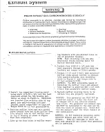
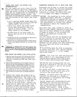
Page 48: ... shield above exhaust tube and slide muffler down into exhaust tube so that muffler rest on top of housing as shown i n Figure Push down completely 5 Line up the four holes in muffler mount f ing brackets with pre drilled holes on top of generator housing NOTE Self clinching nuts are pre positioned inside housing panel for muffler mounting bolts 6 Install four 5 I6 I8 x 3 4 inch hex head capscrews...

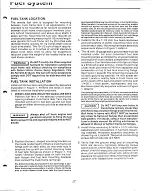
Page 49: ... the mounting bracket should rest against the side of the fuel tank and the wider surface area ol the mounting bracket surface with rubber Isolation pad should be relatively close to radius of truck frame rail See detail A in Figure 1 If not new 3 8 Inch mount ing holes will have to be spaced and drilled In fuel tank flange as required so that fuel tank is held securely in position Install 5 16 18...

Page 50: ...ent fire and explosion hazard and do NOT smoke N O T E NO WELDING OR DRILLING REQUIRED TO INSTALL FUEL TANK TORQUE ALL SIX 5 16 M O U N T I N G BOLTS AT 24 INCH POUNDS 2 7 N m ON A L U M I N U M TANKS DETAIL C HARDWARE ASSEMBLY SEQUENCE FOR STATIC GROUND LEAD CONNECTION TO TRUCK FRAME F I G U R E F U E L TANK I N S T A L L A T I O N ...

Page 51: ...70 flare fittings on remote fuel tank Direction of fuel tank fittings must be adjusted during installation to prevent kinks or sharp beris i n either supply or return line Provisions can be made to u t i l i z e the truck fuel tank to supply the auxiliary generator set i f the truck chassis space i s not available to install the remote fuel tank or i f a larger fuel supply i s desired For operatio...

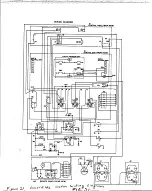
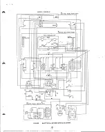
Page 52: ...WIRING DIAGRAM CONTROL PANEL BACK VIEW FIGURE ELECTRICAL SYSTEM WIRING DIAGRAM ...

Page 53: ......

Page 54: ......

Page 55: ......

Page 56: ... r n S i 5 ii 1 ...

Page 57: ...31 Pl H r m m m ...

Page 58: ...Ml ...

Page 59: ......

Page 60: ... N ...

Page 61: ......

Page 62: ......

Page 63: ... j ...

Page 64: ...41 ...

Page 65: ... REAR VIEW 1 2 KO 4 PL REMOTE CONTROL CABLE 6 AC REMOTE RCPT CABLE O O FUEL OUT PUEL N 0 U T 0 0 P 0 S N O O N E T 7 16 20 BY 37 FLARE FITTING 2 PL IS ...

Page 66: ... I ...

Page 67: ......

Page 68: ...WIRING DIAGRAM CONTROL PANEL BACK VIEW A2 REMOTE PANEL REAR VIEW ...

Page 69: ...rt ...

Page 70: ......

Page 71: ......

Page 72: ...v9 ...

Page 73: ...i sac aB33 jBeTWJa k_ j SERIES RDJA MM GenSet 3 0 kW Installation Guide Auxiliary Power Generators For Tmcks Over The Rail Mount ONL Y IMPORTANT Read Through Entire Installation Guide Prior To Actual Installation 972 0625 11 82 ...

Page 74: ...onductor of electricity and should be removed when working on electrical equipment DO NOT PLUG MOBILE PORTABLE OR STANDBY SETS DIRECTLY INTO A HOUSE RECEPTACLE TO PROVIDE EMERGENCY POWER It is possible for current to flow from generator into the utility line This creates ex treme hazards to anyone working on lines to res tore power Use extreme caution when working on electrical components High vol...

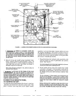
Page 75: ...g Panel Installation ELECIRICAL S Y S T E M WIRING DIAGRAM Connecting GenSet To Truck Batteries FINAL C O M P A R T M E N T A S S E M B L Y COOLING S Y S T E M 3 EXHAUST S Y S T E M FUEL S Y S T E M INSTALLATION FIGURE 1 TYPICAL AUXILIARY G E N E R A T O R SET INSTALLATION IF Y O U H A V E ANY QUESTIONS C O N C E R N I N G T H E INSTALLATION P R O C E D U R E S C O N T A C T T H E O N A N DISTRIBU...

Page 76: ... locally prior to starting the actual installation This generator set i s shipped from the factory completely assembled within the insulated compartment housing for pro tection during shipping Some housing panels and internal compartment wiring require disassembly prior to installing the generator set i n place over the truck frame r a i l s WARNING ONAN RECOMMENDS THAT GENERATOR S E T INSTALLATIO...

Page 77: ...ical beveled washers exactly as shown i n Figure 3 two on each mounting bolt i6 total FIGURE 6 Correct Exhaust Tube Adjustment 6 FIGURE 3 Conical Washer Assembly 3 Be sure to install interconnecting cooling system hoses between truck engine and generator set properly Engine hose connections w i l l vary de pending on truck engine and manufact urer See Figure 4 Positive battery cable routing and co...

Page 78: ... Supply line Coipiection Size SAE 4 370 Flare NOTE Refer to auxiliary generator set Operator s manual f o r complete engine generator specifications EXHAUST GAS IS DEADLY Exhaust gases contain carbon monoxide poisonous gas that might cause unconsciousness and death It is an odorless and colorless gas formed during combustion of hydroca bon fuels Symptomkof carbon monoxide poisoning are Dizziness H...

Page 79: ...t i s de signed f o r Over the Rails mounting ONLYI Distance X listed in Table 1 when measuring for installation MUST be maintained to allow for any truck maneuver in order to proceed with any Over t h e R a i l i n s t a l l a t i o n Refer to Figure 9 when measuring distance X TABLE 1 23 3A in S C E TRAILER King Pin Distance Inches Mininum Space X Inches T r a i l f i r TVTM King Pin Distance In...

Page 80: ...ended practices of the American Trucking Association Maintenance Council The p h y s i c a l s i z e p r i m a r i l y d e p t h o f the g e n e r a t o r compartment r e q u i r e s a MININUM UNOBSTRUCTED OPEN SPACE o f 2 3 3 4 inches parallel to lengthwise the truck frame rails directly behind the cab Measure along the frame rails in the desired mounting location to verify this space is availabl...

Page 81: ...CAUTION On Cab Over Engine type trucks be sure the cab cross brace clears a l l knockouts selected f o r the routing of wiring battery electr ical cooling and fuel line conn ections ...

Page 82: ...all compartment dimensions are shown i n Figure 7j QARNINC Make certain that housing base plate is adequately supported when setting it in place on frame rails Injury may result if the baseplate should fall ofl frame rails id Jrhig ejns tallat ion procedure 3 Temporarily hold one mounting clamp in positior inside from underneath against top frame rail flange of truck as shown in Figure 13 d e t a ...

Page 83: ...ther chassis components underneath baseplate on each side of truck 4 mounting clamps t o t a l Instail our mounting clamps with spacers as required two on each side under top flange of truck frame rails using l 2 13 x 2 inch hex head cap screws and two special 1 2 inch conical washers on each cap screw positioned as shown in Figure 3 detail B Tighten all eight capscrews until conical washers are f...

Page 84: ...f t hand side of the compartment housing can be installed after a l l AC and D C wiring i s completed inside the generator set control panel and through the rear panel of compartment housing as outlined under Compartment Electrical Requirements following FIGURE 14 Compartment Reassembly Replace the right hand side panel of the compartment housing by installing three 3 8 16 x 3 4 inch hex head cap ...

Page 85: ...rical wiring CAUTION Do NOT drill any additional new holes In the truck frame rails or cross support frame members for routing wiring through Any existing holes used for routing of wiring should be protected with grommets Use water tight strain relief connectors 1 2 inch or 3 4 inch whenever wiring passes through any exterior panel cab wall or truck cab compartment Use Romex connectors only i n t ...

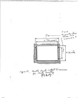
Page 86: ... optional k i t contains a l l required AC and DC wiring cable connectors ter minals and step by step installation in structions I t does NOT contain mounting hardware due to location variations and size of hardware required W A R N I N G Do NOT install remote starting panel without the remote control box housing A potential shock hazard exists because of the exposed terminals of the AC receptacle...

Page 87: ...ALL 1 8 SHEET METAL WATER TIGHT STRAIN RELIEF CONNECTOR t o o M W I REMOTE STARTING PANEL REAR VIEW 1 2 INCH ROMEX CONNECTORS 2 EEDER CABLE _ h c V U i Cfc u c ffc rv o v _ be LK d o V r t FIGURE 18 Remote Control Generator Set Pictorial Wiring Diagram ...

Page 88: ...ost d i r e c t path between genset and remote control panel l o c a t i o n Stay along the inside of the truck frame r a i l s where possible Secure cables every 18 inches along the run with insulated hold down clamps closer together in bends and near high heat sources Use nylon tie wraps as re quired in between clamps Use the most direct wire routing possible to minimize wire length required rh ...

Page 89: ...tral load conductors connected to a ground fault pro tected circuit breaker The AC receptacle box if not water proof must be installed inside a weather protected area such as a tool box stor age compartment or sleeper cab WARNING A l 1 A C c o n v e n l e n c e receptacles regardless of use must be protected by ground fault protection devices for safety Any cold weather starting aids may be connec...

Page 90: ...NOTE Barrel connectors would not be required on the circuit breaker i f two separate AC Hot load wires are connected to the same circuit breaker This w i l l f i l l the set screw terminal enough to allow for good clamping force CAUTION Be careful not to overload circuit breaker i f more than one AC load circuit i s connected to the same circuit breaker 4 Neutral and ground conductors white and gr...

Page 91: ...WIRING DIAGRAM CONTROL PANEL BACK VIEW FIGUHEt ELECTRICAL SYSTEM WIRING DIAGRAM IL ...

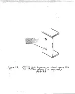
Page 92: ...end of 16 inch truck electrical bonding strap must be attached to a convenient bolt on the side of the _ t r u c k frame rail If no existing bolt or bolt hole is 7 available installer must drill a new hole in the side of the truck frame rail within reach of the electri cal bonding strap Refer to Pre lnstallation Sec tion forspecial precautions PRIORtodrillingany new holes in truck frame rail C A U...

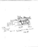
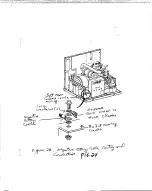
Page 93: ... control and the truck battery rack w i l l change The previous recommendations for battery cable size and routing do not change rt o kH f o i t tfrvy Ie J _ FIGURE 23 Insulating Positive Battery Terminal Connection FIGURE 24 Battery Cable Routing and Connections 12 ...

Page 94: ...ceptacle on top of generator end of the set inside the compartment 3 Two tether straps supplied i n accessory kit must be installed one on each hous ing side panel to control movement of the set when the truck i s i n operation Locations shown i n Figure S are f o r reference ONLY The tether straps can be installed under any one of the five 3 8 inch hex head capscrews which secure housing side pan...

Page 95: ...bers under load and due to vibration Any new holes drilled in frame rails cannot be located any closer to frame flanges than the existing bolt pattern regard less of frame material NO drilling whatsoever is allowed in the top or bottom frame rail flanges Marks for any new FARPIE holes must be made with pencil lead Do NOT use a sharp tool for making scribe marks to prevent cracks from starting or e...

Page 96: ...I 5 11 s i 8 ill c i J 1 1 I ...

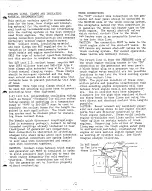
Page 97: ...ier mounting brackets and torcue toiSi oot pounds Install 1 1 2 inch U bolt tyre autor o tiv muffler clamp around T uffler to exhaust tube connection under rain shield as shown i n Figure 4 and torque r uts tc 11 foot pounds l5 N M CAUTION The ONLY acceptable meand of fastening the muffler i n l ex r i exhaust tube together i s approved SAE l l 2 inch U bolt type automotive r uffler clamp 8 Rechec...

Page 98: ...enerator set compartment isolates the set cooling system from the truck engine cooling system when the generator set i s NOT running There i s a variable pressure control o r i f i c e i n the generator set cooling system which isolates the generator set cooling system rom the higher pressure i n the truck cooling ystem when both the generator set and the truck engine are running There i s a check...

Page 99: ...onnectthe AC plug of the generator set coolant flow solenoid valve into an external 115 volt AC source to open the valve for coolant flow 5 Start truck engine and run until clean coolant flows out of the open petcock vent on the gen erator set engine Then close petcock on genera tor set No coolant ilow may indicate incorrect cooling line con nections between truck cooling system and generator set ...

Page 100: ...o allow access to fill spout and provision for reading fuel level gauge along one end on top of fuel tank If a step plate is used on truck frame ahead of fifth wheel area access holes may have to be punched in step plate for those items OVER THE RAIL INSTALLATIONS The fuel tank cannot be mounted underneath the generator set compartment or outside the truck frame rails The 16 1 2 inches minimum of ...

Page 101: ...l tank mounting brackets must contact the truck frame rail flange Pre drilled mounting hole location in fuel tank flange is usu ally adequate to securely fasten fuel tank in most installations Some trucks may have variations in width of frame rail flange area or width between truck frame rails that could require spacing and drilling new mounting holes in fuel tank flanges When installed the vertic...

Page 102: ...uck DETAIL B STATIC GROUNDING LEAD CONNECTION AND HARDWARE ASSEMBLY SEQUENCE AT FUEL TANK SIX 5 16 18X 1 1 2 MOUNTING BOLTS W A R N I N G Always shut off truck engine and generator set prior to filling the fuel tank to prevent fire and explosion hazard and do NOT smoke NOTE NO WELDING OR DRILLING REQUIRED TO INSTALL FUEL TANK TORQUE ALL SIX 5 16 MOUNTING BOLTS AT 24 INCH POUNDS 2 7 N m ON ALUMINUM...

Page 103: ......

Page 104: ...xnv MaiA aais ...

Page 105: ......

Page 106: ......

Page 107: ...ci ri V ...

Page 108: ......

Page 109: ... 1 ...

Page 110: ...f ...

Page 111: ...SIDE VIEW AUX ...

Page 112: ...V A vs ...

Page 113: ...5 I Qc 3 ...

Page 114: ...I r k J ul V ...

Page 115: ...10 t i t ...

Page 116: ... ...

Page 117: ...ST p Q 6 ...

Page 118: ...21 TflvC mfirMs ft fr S ...

Page 119: ...11 c4 i t ...

Page 120: ... 0 ...

Page 121: ...E AT 15 FOOT POUNDS 20N m CLAMP ISOLATOR GASKET C MOUNTING ISOLATOR GASKET PART OF HOUSING BASEPLATE x 9 C L y JLficyXJLAJ y _ NUMBER OF 1 4 AND 1 16 INCH SPACERS PER MOUNTING CLAMP NOT TO EXCEED 3 4 INCH MAXIMUM THICKNESS STEP 3 ...

Page 122: ... 1 sc i 1 I 41 S I ...

Page 123: ... 1 ...

Page 124: ......

Page 125: ......

Page 126: ...W t 11 r c v j ...

Page 127: ...0 1 ...

Page 128: ...73 R3 R4 K2_ Wl W2 HTR I Al CONTROL BOX FRONT VIEW CIRCUIT BREAKER ASSY CBI CBS GND a NEUTRAL BAR CBZ 0 o b CB4 GFI CR2 o W GRN TT 75 71 Ts TOGI TB W4 B T I HTR 2 CRS K6 ary ir i LJ R 2 6 L Q i Tl W7 S4 SS S7 I HTR 3 6 5 VRI AC A2 REMOTE PANEL REAR VIEW JI GRN W H T BLKJkH F 7 6 ...

Page 129: ...01 ...

Page 130: ......

Page 131: ... 1 ...

Page 132: ...HOLE AND LOCATE CENTER S o NOT USE A SHARP TOOL FOR SCRIBING MARKS ON FRAME RAILS pi 6 4 1 J ...

Page 133: ...ng truck battery terminals attach negative last Check terminals at battery and on set for clean tight connections Re inspect periodically Vehicle chassis truck frame ground and the battery and genera tor set ground should all be electrically connected to be a 0 ground potential All Onan units are designed for negative ground application CAUTIO CONNECTING BATTERY CABLES For 24 volt truck battery st...

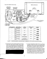
Page 134: ...mote Panel Running Time Meter and Switch S1 Integral Running Light Black Ring F I G U R E 4 C O N N E C T I N G R E M O T E S T A R T I N G PANEL T O G E N E R A T O R S E T AND L O A D D I S T R I B U T I O N P A N E L 3 Route the DC control cable along the inside of the truck frame rails where possible Secure cable every 18 inches along the run with insulated hold down clamps closer together in ...

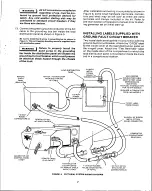
Page 135: ...he kit Refer to pre start section of Operator s manual prior to start ing generator set on initial start up INSTALLING LABELS SUPPLIED WITH GROUND FAULT CIRCUIT BREAKER Two loose labels are supplied in conjunction with the ground fault circuit breaker Attach the GFCB label to the inside cover of the load distribution panel on the hinged cover Attach the Test Reminder label on the inside door of th...

Page 136: ... or silicone rubber sealant to seal around all openings made for electrical wiring CONNECTING REMOTE PANEL TO GENERATOR SET he remote control panel allows the driver to start the lenerator set within the cab area of the truck The panel contains start stop and on off alarm rocker switches running time meter buzzer alarm and one AC duplex receptacle The control wiring in this kit includes all wire a...

Page 137: ...e connected to the closest 6 terminal grounding bar located on each side of the control panel Barrel type connectors are not required on any grounding bar connections ftq 0 JL of RETAINER NUT INSIDE COMPARTMENT WATER TIGHT STRAIN RELIEF CONNECTOR COMPARTMENT REAR WALL 1 8 SHEET METAL Poor Oftv ll jBULKHE D CQNSECTOFKIZS FCARE FU SUPELY LINE PR SM R EKlOTEVCMI o VOA OL 4 S Vjt c lc Qa v ytJ Co K A ...

Page 138: ... e d See page _ F i g u r e Choose a tether location that is close or conve nient to an existing frame bolt or frame hole Use at least a 3 8 inch Grade 5 bolt for attaching tether to truck frame rail If no existing bolt or bolt hole is available installer must drill a new hole inthe side 1 of the truck frame rail Refer to Pre lnstallation Section for special precautions PRIOR to drilling any new h...

Page 139: ...ator set compartment isolates the set cooling system from the truck engine cooling system when the generator set i s NOT running There i s a variable pressure control orifice in the generator set cooling system which isolates the generator set cooling system from the higher pressure i n the truck cooling system when both the generator set and the truck engine are running There i s a check valve in...

Page 140: ...ruck engine and generator set MUST be insulated i n order to avoid excessive heat loss and to heat the truck engine adequately for cold weather starting Proper connections are c r i t i c a l for the generator set to function properly without overheating TRUCK CONNECTIONS The OUT coolant line connection on the gen erator set rear panel should be connected to the SUCTION side of the truck cooling s...

Page 141: ...AC plug of the generator set coolant flow solenoid valve into an ex ternal 115 volt AC source to open the valve for coolant flow CAUTION Do NOT run the auxiliary gen erator set to prime the cooling system Start truck engine and run u n t i l clean coolant flows out of the open petcock vent on the generator set engine Then close petcock on generator set CAUTION No coolant flow may indicate incorrec...

Page 142: ...bove exhaust tube and slide muffler down into exhaust tube so that muffler rest on top of housing as shown i n Figure Push down completely 5 Line up the four holes i n muffler mount ing brackets with pre drilled holes on top of generator housing ftOTE Self clinching nuts are pre positioned inside housing panel for muffler mounting bolts 6 Install four 5 I6 I8 x 3 4 inch hex head capscrews through ...

Page 143: ...ace of the mounting bracket should rest against the side of the fuel tank and the wider surface area of the mounting bracket surface with rubber Isolation pad should be relatively close to radius of truck frame rail See detail A In Figure 1 If not new 3 8 Inch mount ing holes will have to be spaced and drilled in fuel tank flange as required so that fuel tank Is held securely in position 3 Install...

Page 144: ... generator set prior to fllling the fuel tank to prevent fire and explosion hazard and do NOT smoke NOTE NO WELDING OB DRILLING REQUIRED TO INSTALL FUEL TANK TORQ UE ALL SIX 5 16 M O U N T I N G BOLTS AT 24 INCH POUNDS 2 7 N m ON A L U M I N U M TANKS DETAIL C HARDWARE ASSEMBLY SfcOUENCE FOR STATIC GROUND LEAD CONNECTION TO TRUCK FRAME FIGURE FUEL TANK INSTALLATION ...

Page 145: ... l tank f i t t i n g s must be adjusted during i n s t a l l a t i o n to prevent kinks or sharp beris i n either supply or return l i n e Provisions can be made to u t i l i z e the truck f u e l tank to supply the a u x i l i a r y generator set i f the truck chassis space i s not available to i n s t a l l the remote f u e l tank or i f a larger f u e l supply i s desired For operation i n col...

Page 146: ...WIRING DIAGRAM CONTROL PANEL BACK VIEW FIGURE ELECTRICAL SYSTEM WIRING DIAGRAM 11 ...

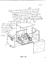
Page 147: ...ed hold down clamps and or nylon tie wraps as required 9 Route the AC cable through a 1 2 inch Romex connector at the entry point knock out going intogenerator sej panel as shown in Figure control 10 Cut cable to required length making sure there is enough extra wire inside load distribution panel to make all connections Allow some slack in the wiring for movement from vibration to prevent breakag...

Page 148: ... 1 5 m p circuit breaker with built in ground fault circuit i n q terrupter protection The branch load ci rGui ts sheul d JDe q ualiy d i vi ded be fee eiLjtJtje xeake2 _usi ng wi re si zed___ a aording_tcLJkhe _maperage of each oadJ The AC feeder cables from each individual load circuit must be adequately sized and properly routed through the generator set compartment housing and into the set con...

Page 149: ...odes and follow National Electrical Code standards and re commended practices A qualified electrician should Inspect all wiring Routeall ACand DC wiring along the inside of the truck frame rails where possible Keep away from rotating or moving shafts and linkages of the truck Use insulated hold down clamps spaced approximately every 18 inches closer together in bends or near high heat sources Plas...

Page 150: ...OR 332 0430 14 GA MUST BE CRIMPED ON THE HOT LEADS OF LOAD CIRCUITS WHEN 14 GA WIRE IS USED 5 BALANCE LOADS AT THE LOAD CENTER ON THE 6 5 NH 6 BARREL CONNECTOR 332 0417 IOGA FORTHE 6 5 NH 332 0418 8GA FOR TWE4 0BFA MUST BE CRIMPED ON THE HOT LEADS R t r OES QTY DESCR PT Al CONTROL PANEL ASSY AZ 1 LOAD CENTER A3 I HANDY BOX I RECEPTACLE DUPLEX I COVER DUPLEX RCPT CBI I BREAKER CIRCUIT GFI I5A CB2 1...

Page 151: ...urces Use nylon tie wraps as required in between clamps On cab over engine type truck chassis all routing of any wiring regardless of type or function MUST be long enough and routed in such fashion that raising and lowering of cab for access to engine will NOT interfere with wiring Allow slack at the nose hinged point of the cab for raising cab as required CONNECTING FEEDER CONDUCTORS TO DISTRIBUT...

Page 152: ...as possible into 3 4 inch water tight metal strain relief connector with 45 angle elbow Attach an uninsulated solderless ring terminal on the end of the green ground con ductor of the supply cable after it is routed through the metal srain relief connector 3 Install the 3 4 inch water tight metal strain relief connector and supply cable into the lower knock out of the generator set AC junction box...

Page 153: ...l remote panel o m i n i m r z e P S n e p a c l e i n Ihe Secure cable everv T n 9 a 1 required E l a t e d h o l l S n a n 9 h e S raps as required a m p s a n d r nylon tie required as each conn 0 minals are a m T c r e l conductors to the around faul circM p Z h a S h e bullw markmg on the circuitT N o e e white location ol the white conr t a f e r o r h e correct ctor goes to screw term C 0 r...

Page 154: ...and method of mounting wall of shelf deter mines which connector to use See Figure On cab over engine type truck chassis all routing of any wiring regardless of type or function MUST be long enough and routed in such fashion that raising and lowering of cab for access to engine will NOT interfere with wiring Allow slack at the nose hinged point of the cab for raising cab as required WARNING D o N ...

Page 155: ...15 FOOT 3 CONDUCTOR 14 GAUGE TYPE SO AC CABLE GENSET Termi n a l No REMOTE PANEL lA j T e r m i n a l No 1 CIRCUIT FUNCTION WIRING COLOR CODE i Ground White 2 Stop Red 3 3 Start Green 4 Remote Alarm Signal Orange 5 D i e s e l Preheat Blue 6 Running Time Meier and Switch S1 Integral Running Light Black FIGURE REMOTE STARTING PANEL INSTALLATION 33 ...

Page 156: ...sions have been made inside the generator set control after some minor modifications to quickly and easily convert the set s wiring when necessary Control and battery cable connections at both the generator set control and the truck battery rack w i l l change The previous recommendations for battery cable size and routing do not change Consult factory i f necessary to convert the auxiliary genera...

Page 157: ...es SAE 37 flare feedthrough connector in compart 4 ment rear wall I f i JrW ment rear wall I f Installs in generator set fuel pump inlet bottom hole Compartment inside fuel line between fuel pump and com partment rear wall feedthrough connector y l I Connect to oil drain fitting on generator set for changing oil j EXHAUST SYSTEM DESCRIPTION Exhaust down tube 12 1 2 long Muffler Asbestos gasket 5 1...

Page 158: ...on hardware is j included These items should also be on hand prior to actually performing any installation T h e j QTY 2 f AsReq Water tight 3 4 metal strain relief 331 0237 y J Four in generator compartment rear wall one into generator w V J If i t J set AC junction box one into load distribution panel for main i v v feeder conductor 7 u t I r Z Watertight 1 2 metal strain relief 331 0236 f i i V...

Page 159: ... plated contacts 323 1222 Weather protective cover for external AC receptacle 323 1223 AC receptacle box heavy duty 330 0118 Water and dust tight 3 prong hospital grade connector with nickel plated contacts and rubber O ring seal v v t y Double 00 2 0 battery cable up toJO ft in length Positive and negative battery cables 334 0885 S WHERE USED Optional AC duplex outlet for plug in loads Optional w...

Reviews: