4
3. Check proper connection and support of compressed air
lines to the dryer; check bypass valve system, if installed.
4. SLOWLY pressurize the dryer. The outlet valves of the dryer
should be closed to prevent flow through the dryer.
5. Turn on the main electrical power to the dryer.
6. Ensure adequate ventilation for air cooled dryers.
7. Do not operate the dryer with any dryer cabinet panel
removed.
Cooling air flow across the condenser may be reduced
if a dryer panel has been removed while the dryer
is operating, resulting in the dryer not functioning
properly and/or dryer failure. Failure to follow these
instructions may result in a non-warrantable dryer
failure.
To start dryer
IMPORTANT: Energize dryer for 24 hours prior to starting
refrigerator compressor! Failure to follow these instruc-
tions may result in a non-warrantable compressor failure.
1. Turn the power switch to ON. The refrigerant compressor
will turn on.
2. Allow the dryer to run 15 minutes. Confirm that the tem-
perature indicators are in the green zone.
3. SLOWLY open the dryer outlet valves permitting flow
through the dryer.
4. Confirm that condensate is discharging from the drain valve
by pressing the “Push-to Test” button (on drain).
5. Confirm that the inlet air temperature, pressure and airflow
to the dryer meet the specified requirements (see Engi-
neering Data section).
6. Confirm that the condensate lines from the drain valve
discharge into a collection tank or an environmentally ap-
proved disposal system.
The FLEX dryer is designed to run and stop repeatedly. Let the
FLEX dryer operate even when the demand for compressed air
is interrupted; the FLEX dryer will not freeze up.
Shutdown
When the dryer must be shutdown for maintenance or other
reasons, use the following procedure.
1. Turn off the power switch.
2. Disconnect the main power supply.
3. Lock out and tag the power supply in accordance with OSHA
requirements.
If mechanical repairs are to be made or service is performed,
vent the internal pressure of the dryer to atmospheric pressure.
Restart the dryer according to the start-up instructions.
Disconnect power supply and depressurize dryer before
servicing. Dismantling or working on any component of
the compressed air system under pressure may cause
equipment failure and serious personal injury.
Operation
1. To start the dryer, turn on the (a) dryer on/off switch.
2. When the refrigeration compressor and the condenser fan
are running, the cold refrigerant in the chiller (evaporator)
cools the liquid Phase Change Material (PCM) which gradu-
ally solidifies. During this time, the refrigeration compressor
running light (c) is illuminated on the LCD window.
3. Energy saving percent (e) is displayed on the LCD window
by calculating dryer running time and refrigeration com-
pressor operating time.
4. Pressure dew point level (f) is displayed on the LCD window.
5. Dryer running time (h) is displayed on the LCD window while
the power is on. Pressing (g) will toggle the compressor
running time where the dryer running time (h) was dis-
played. When the (j) button is pressed and held for over 10
seconds, dryer and compressor running times are erased
and displayed “0 H”. (timer reset)
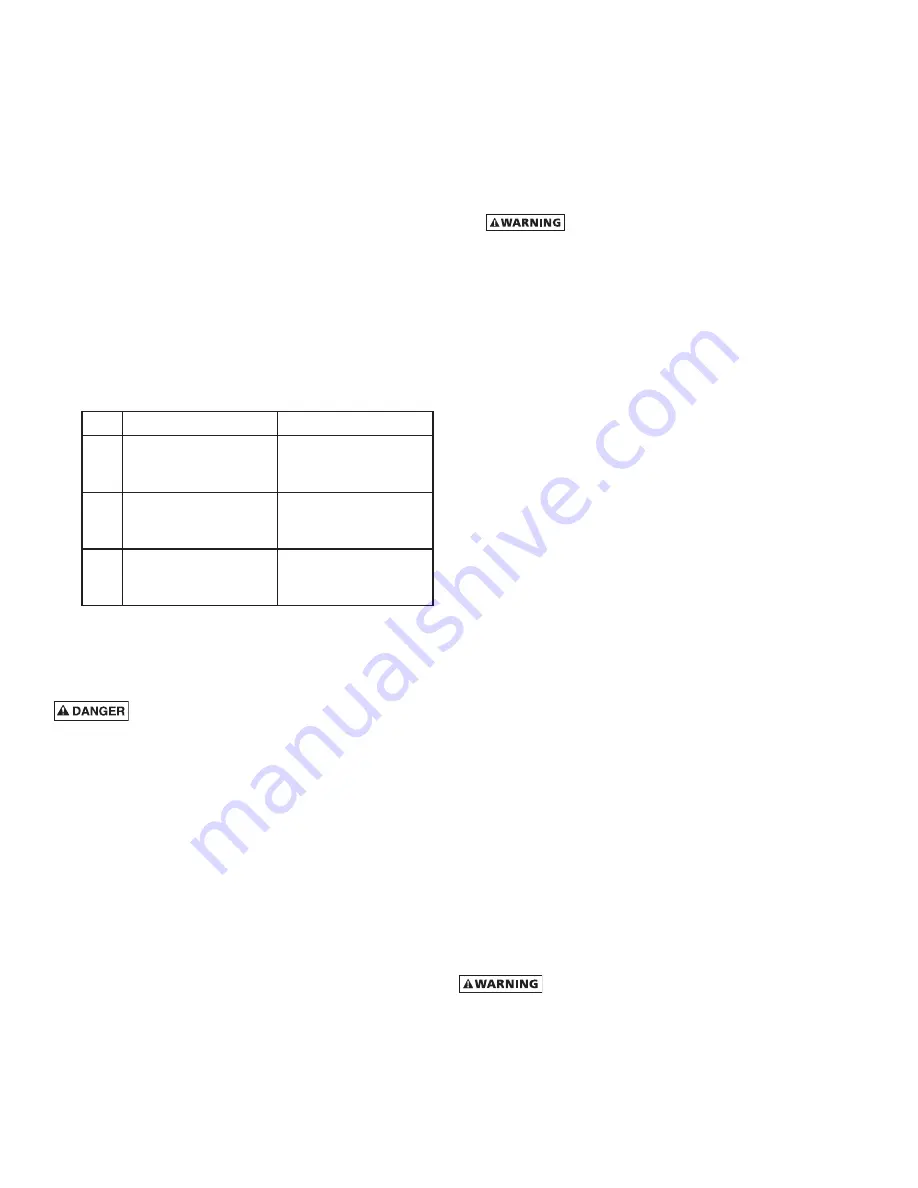
6. Check the dryer operating status when the alarm light (b)
blinks according to Table 1 below.
No. Alarm display
Description
1
lamp (b) blinks rapidly
and “E01” is displayed
on (h)
Ref. compressor has
no signal
2
lamp (b) blinks and
“E02” is displayed on
(h)
Temperature sensor
signal open
3
lamp (b) light is on
“E03” is displayed on
(h)
Drain valve has some
trouble
Table 1. Alarm display mode
START-UP/OPERATION
Never use the disconnect switch to shut down the dryer
for an extended period of time (except for repair). Failure
to follow these instructions may result in a non-warrant-
able compressor failure.
IMPORTANT: Energize dryer for 24 hours prior to starting
refrigerator compressor! Failure to follow these instruc-
tions may result in a non-warrantable compressor failure.
Follow the procedure below to start your dryer. Failure to follow
the prescribed start-up procedure will invalidate the warranty.
If problems arise during start-up, call your distributor. Before
repair, vent the internal pressure of the dryer to atmospheric
pressure.
Before starting dryer
Drain connections must be made before the dryer can be op-
erated. The dryers are fully automatic and require no auxiliary
controls.
1. Turn the dryer on/off switch to off.
2. Check that the main electrical supply voltage matches the
voltage specified on the dryer data plate.
MCGUIRE AIR COMPRESSORS INC
1-888-229-9999
MCGUIRE AIR COMPRESSORS INC
1-888-229-9999


