background image


ACPI supporting for OS Directed Power Management 
Ring-in Wake up:

 When Ring-In the system can wake up from SMI Mode.

Ring-in Power On:

 When Ring-In the system can power on automatic by this function.

Wake on LAN: 

When Wake on LAN the system can power on automatic by this function.

RTC Power On:

 Enabled RTC Power On function, you can setting RTC alarm to power on

the system at the time length you setting .

Power Button:

 Press the button will place the system power on/off.

Support Software Power OFF Function.

Power   Support:

  Efficient   PWM   switching   power   instead   of   traditional   Linear   Voltage

Regulator to prevent power component from being burned-out.

Meets PC99 Requirements.

Optional IRDA and PS/2:

 This motherboard supports an dedicated 16C550 standard UAR

T,

s

upporting  infrared communication module for wireless interface and PS/2 mouse cable set.

USB Port Connector: 

This motherboard supports two USB port connectors and extra two USB

interface for total of four USB devices.

PC Health  Monitoring   :

  To  track  PC CPU  temperature,  system  voltage   and  fan   speed.

When current temperature over warning temperature system will have alarm to warning.

ATX Form Factor:

 Dimensions 30.5cm x 19.0cm.

2

Summary of Contents for 771AS

Page 1: ...or omissions which may appear in this document nor does it make a commitment to update the information contained herein NO G03 771ASR1A Release date FEB 2000 Year 2000 compliant Trademark AMD is regis...

Page 2: ...Settings 6 2 6 System Memory DRAM 8 2 7 Central Processing Unit CPU 8 2 8 Expansion Cards 9 2 9 External Connectors 10 Chapter 3 AWARD BIOS SETUP 14 3 1 Standard CMOS Features 15 3 2 Advanced BIOS Fea...

Page 3: ...than 90dB 16 Bit Stereo Full Duplex Codec 4 Analog Line Level Stereo Input High Quality CD Input with Ground Sense Stereo Line Level Output Multi Speed Support Provide 100MHz Clock and Double Date Rat...

Page 4: ...r OFF Function Power Support Efficient PWM switching power instead of traditional Linear Voltage Regulator to prevent power component from being burned out Meets PC99 Requirements Optional IRDA and PS...

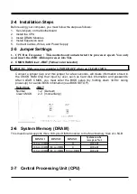
Page 5: ...e damage to your board Be sure there are no shipping and handling damages on the board before proceeding After opening the mainboard carton extract the system board and place it only on a grounded ant...

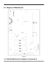
Page 6: ...2 2 Diagram of Motherboard Figure 2 1 2 3 Quick Reference for Jumpers Connectors 4...

Page 7: ...r 40 Pin Block p 12 IDE2 Secondary IDE Connector 40 Pin Block p 12 IDELED IDE activity LED 2 Pin Connector p 13 JP15 Front Panel Connector 16 Pin Block p 13 IR1 Infrared Module Connector 10 Pin Block...

Page 8: ...ou CLEAR CMOS Connect a jumper Cap over this jumper for a few seconds will clears information stored in the CMOS RAM Chip that input by user such as hard disk information and passwords After CLEAR CMO...

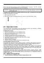
Page 9: ...the card on the slot with the screw you remove in step 4 7 Replace the computer s cover 8 Setup the BIOS if necessary 9 Install the necessary software drivers for your expansion card Assigning IRQs f...

Page 10: ...stem board until the front panel switch is momentarily pressed Press this switch again will turn off the power to the system board 2 PS 2 Mouse PS 2 Keyboard Connector K B CONN If you are using a PS 2...

Page 11: ...is Connector are 3 phone Jack for LINE OUT LINE IN MIC and a 15 pin D Subminiature Receptacle Connector for joystick MIDI Device Line out audio output to speaker Line in audio input to sound chip MIC...

Page 12: ...hard disk ribbon cable After connecting the single plug end to motherboard connect the two plugs at other end to your hard disk s If you install two hard disks you must configure the second drive to...

Page 13: ...der to prolong the life of the system s power supply See the figure below 15 Keyboard lock switch lead PWRLED This 5 pin connector connects to the case mounted key switch for locking the keyboard for...

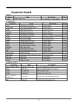
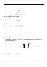
Page 14: ...tton connector PWRBTN1 20 CD Audio in connector CD_IN1 CD_IN2 These are the connectors for CD Audio Input signal please connect it to CD ROM CD Audio output connector 21 Wake On LAN connector WOL1 12...

Page 15: ...Wake On LAN Function worked only when power supply support 5VSB more than 750mA current Chapter 3 13...

Page 16: ...pset Features Integrated Peripherals Power Management Setup PnP PCI Configurations PC Health Status Frequency Voltage Control Load Optimal Defaults Load Standard Defaults Set Supervisor Password Set U...

Page 17: ...exit setup See section 3 12 for the details 3 1 STANDARD CMOS FEATURES The items in Standard CMOS Features Menu are divided into many categories and each category may includes more than one setup ite...

Page 18: ...l Cache Enabled CPU L2 Cache ECC Checking Enabled Quick Power On Self Test Enabled First Boot Device Floppy Second Boot Device HDD 0 Third Boot Device LS ZIP Boot other Device Enabled Swap Floppy Driv...

Page 19: ...boot device that is available if the other fails Swap Floppy Drive If the system has two floppy drives you can swap the logical drive name assignments The choice Enabled Disabled Boot Up Floppy Seek S...

Page 20: ...be if you discovered that data was being lost while using your system CMOS Setup Utility Copyright 1984 1999 Award Software Advanced Chipset Features Bank 0 1 DRAM Timing SDRAM 10ns Bank 2 3 DRAM Tim...

Page 21: ...led USB Keyboard Support Disabled OnChip Sound Auto Sound Function Press Enter OnChip Modem Auto Onboard FDC Controller Enabled Onboard Serial Port 1 Auto Onboard Serial Port 2 Auto UART 2 Mode Standa...

Page 22: ...ght 1984 1999 Award Software Power Management Setup ACPI function Enabled Power Management Press Enter ACPI Suspend Type S1 POS PM Control by APM Yes Video Off Option Suspend Off Video Off Method V H...

Page 23: ...e of system inactivity all devices except the CPU will be shut off The choice Enabled Disabled HDD Power Down When enabled and after the set time of system inactivity the hard disk drive will be power...

Page 24: ...ically configure all of the boot and Plug and Play compatible devices If you have trouble in assigning the interrupt resource automatically you can select manual it will allow you to choose specific r...

Page 25: ...Frequency Voltage Control Auto Detect DIMM PCI Clk Enabled Spreed Spectrum Disabled CPU Host PCI Clock Default Item Help Menu Level Move Enter Select PU PD Value F10 Save ESC Exit F1 General Help F5...

Page 26: ...w will clear any previously entered password from CMOS memory You will be asked to confirm the password Type the password again and press Enter You may also press Esc to abort the selection and not en...

Page 27: ...edly Error Messages One or more of the following messages may be displayed if the BIOS detects an error during the POST This list includes messages for both the ISA and the EISA BIOS CMOS BATTERY HAS...

Page 28: ...ROLLER Cannot initialize controller Make sure the cord is correctly and firmly installed in the bus Be sure the correct hard drive type is selected in Setup Also check to see if any jumper needs to be...

Page 29: ...ed in conjunction with the I O CHANNEL CHECK and RAM PARITY ERROR messages when the segment that has caused the problem has been isolated PRESS A KEY TO REBOOT This will be displayed at the bottom scr...

Page 30: ...s fail 80 HDD reset failed Hard Disk s fail 40 HDD controller diagnostics failed Hard Disk s fail 20 HDD initialization error Hard Disk s fail 10 Unable to recalibrate fixed disk Hard Disk s fail 08...

Page 31: ...Reset keyboard for Winbond 977 series Super I O chips 0Bh Reserved 0Ch Reserved 0Dh Reserved 0Eh Test F000h segment shadow to see whether it is R W able or not If test fails keep beeping the speaker...

Page 32: ...mory I O resource Search for a valid VGA device VGA BIOS and put it into C000 0 24h Reserved 25h Reserved 26h Reserved 27h Initialize INT 09 buffer 28h Reserved 29h 1 Program CPU internal MTRR P6 PII...

Page 33: ...acheable range to smaller one in case the cacheable ranges between each CPU are not identical 4Fh Reserved 50h Initialize USB 51h Reserved 52h Test all memory clear all extended memory to 0 53h Reserv...

Page 34: ...pressed 74h Reserved 75h Detect install all IDE devices HDD LS120 ZIP CDROM 76h Reserved 77h Detect serial ports parallel ports 78h Reserved 79h Reserved 7Ah Detect install co processor 7Bh Reserved...

Page 35: ...Enable L2 cache 2 Program boot up speed 3 Chipset final initialization 4 Power management final initialization 5 Clear screen display summary table 6 Program K6 write allocation 7 Program P6 class wr...

Page 36: ...Run X KX133 HEALTH SETUP EXE Windows 98 Run X KX133 HEALTH SETUP EXE Sound Driver For Windows 95 98 user before you install Sound Driver please remove PCI Multimedia Audio Device under OTHER DEVICE o...

Page 37: ...ort Pin 2 3 for 3 to 5 seconds on JBAT to clear CMOS 1 Turn on the computer 2 Hold Down key immediately after turning on the computer 3 Main Menu on Display Pg 15 Fig 3 4 Select Standard CMOS Feature...

Page 38: ...m Windows 95 98 2 From Windows 95 98 3 From Windows 95 98 36 Quick Installation Guide Driver Installation 4 in 1 IDE VXD AGP ACPI Health Monitor Start Run Insert Driver CD Browse KX133 Health Setup So...

Reviews: