background image

Summary of Contents for JH-500 Series

Page 1: ...PROFESSIONAL MIXING DESK...

Page 2: ...reating minimum control room acoustic problems and permitting a clear view into the studio This console was designed for maximum f l exibility and for easy conversion to AUTOMATED CONTROL Each channel...

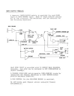
Page 3: ...S CHANNEL ACN QUAD POST PAN AMP QUAD MIX METER BUFFER INDIVIDUAL SEND BUSSES PREAMP ______________________________ PRE POST SEND OUT Each MIKE INPUT is provided with 32 OUTPUT BUSS SELECTOR switches A...

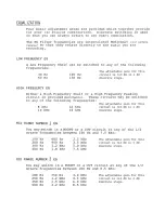
Page 4: ...Peaking circuit is provided Swi tchab1 e These circuits may be switched to any of the following frequencies 8 kHz 10 kHz MID RANGE NUMBER 1 EQ 12 kHz 16 kHz The adjustable gain for this circuit is flO...

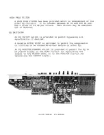
Page 5: ...G An EQ IN OUT switch is provided to permit bypassing all equalization if pesired A movable PATCH POINT is provided to permit the compression or limiting to be connected either before or after EQ An E...

Page 6: ...HE PROGRAMMING for that module only A GREEN LED beside the VCA FADER lights whenever the VCA circuit has been changed to the MONITOR circuit Level controls for the eight SUB GROUPS described in the MO...

Page 7: ...e selected from a POST FADER or a PRE FADER point SENDS I and 2 are controlled by 45rnrn conductive plastic linear faders and are AUTOMATION CA PABLE SENDS 3 and 4 have individual level controls SENDS...

Page 8: ...set of control room speakers An ALTERNA E CENTER switch permits shifting the center of the room from the C ONSOLE to the PRODUCER s DESK Internal pots are provided to set up this alternate center loca...

Page 9: ...ugh the patch panel ECHO RETURN SYSTEMS Four ECHO RETURN systems are provided each with full QUAD PANNING Two of these circuits are in the MASTER module and two are in the COMMUNICATIONS module One of...

Page 10: ...OFF _ GROUP MUTE if assigned to a group MASTER MUTEi f assi gned to MASTER__ o auto mute sw AUTO MUTE BUSS 0 1 _1 READ OR UPDATE from Automation_ J MONITOR MUTE ALL OUTPUTS EXCEPT QUAD MIX QUAD OR GA...

Page 11: ...used A SOLO button associated with each ECHO RETURN circuit is provided which functions exactly like the MONITOR SOLO button on the INPUT OUTPUT module COMMUNICATIONS SYSTEMS There are three communica...

Page 12: ...k in the patch bay and the MIX and TKS switches will feed the externally generated signal into the system METERING 24 VU meters are provided and numbered to correspond to the same numbered OUTPUT BUSS...

Page 13: ...provides a MEMORY for the HIGHEST AUDIO PEAK which occurs on each channel during the time it is operating The ACCUMULATE reading is shown as a lower intensity graph above the TRANSIENT AUDIO reading A...

Page 14: ...7 TAPE MACHINE RETURN 28 8 CHANNEL LINE INPUT 28 Whether Pre EO or Post EQ depends on position of switch on I O Module Whether Pre EQ or Post EQ depends on position of switch on I O Module 9 QUAD MIX...

Page 15: ...he OVRLD light shows that one or more of the VCAs are at maximum gain The four lights with voltages marked bes ide them are monitor ing the power supplied to the console When lighted they indicate tha...

Page 16: ...eter This Spectrum Analysis is made in real time AS YOU HEAR the program on your monitor SPEC I FI CATIONS INPUTS are switch selectable from 8 sources Simultaneous displays of any number of these inpu...

Page 17: ...simple pushbuttons per Channel for ALL FIVE AUTO MATED FUNCTIONS When CHANNEL GROUPING is used three buttons can control the whole group These buttons are already built into the modules and are label...

Page 18: ...ION HAS FOUR MODES WRITE This is accomplished by pushing the VCA button and going through the recording with the controls set as you wish them to be PLAYBAC K None of the desk buttons are used Going t...

Page 19: ...CIR CUIT Input impedan ce to Fade r Nomina l output Signal to no i se Distortion MIXDOWN Better than Nominal au tpu t 24 dBm output Maximum output Into 600 ohms 0 5 THD 1 kHz signal Separation of QUAD...

Page 20: ...1 1 4007 N E 6th Avenue Ft Lauderdale Florida 33334 Phone 305 566 2853 Telex 51 4362...

Page 21: ...AMP _ 24 1 It 5 KI MONI lOR RELA 7 8 I Uf 24V 0 I t O 0_ ___________ Ct OVRO LAMP RELAY SUSS 21V LAMP POoWER RELAY lAMP COMMOII 3 1 01 a_ l QllS UNLESS THERWISE SPECIFIEO 1 1 R TO V UoI A t w 1 ALL C...

Page 22: ...CHANNEL 2 0UT I I I I I K2 RL2 MON 211 I IOOUF I 25V 1 RELAY COMMON rl C 7 R36 15PF R25 R38 IK I IK 24V 4 7K TB MUTE RELAY CHAN 2 I RIGHT REAR R26 3 8 10 1 I IK 4 Mel 7 8 r I C3 I 2001 6 __ 1 I 4 I C...

Page 23: ...22K II0K 033 47K 1 1 I IK 21 LEFT REA R I I j QUA D 0 UT C T R43 12PF R29_ V R45 IK 8 24 10K 3 10 MCI 7 6 C1 2 J R2B IK I 1 CHANN EL 2 I 1 I 1 C4 2001 _ __jE t t_ 1 ___ __ 2 C2 100UF I I _ _ J 10o UF...

Page 24: ......

Page 25: ...PLAY HOUSING JH 528 16 LM 16 Channels Supplied Wired for 28 Channels JH 528 24 LM 24 Channels Supplied Wired for 28 Channels JH 528 28 LM 28 Channels Supplied Wired for 28 Channels 42 CHANNEL FRAMES W...

Page 26: ...em price Fader Writing Strips for JH 528 Frames Installed Below the Straight Line Fader to Hold 1 Paper Leader Tape Fader Writing Strips for JH 528 Frames Installed Above the Stra ight Line Fader to H...

Reviews: