17
How to Operate in Four or Three Channel Mode
How to Operate in Four Channel Mode
How to Operate in Three Channel Mode
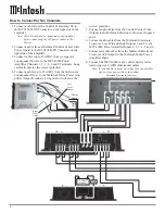
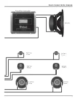
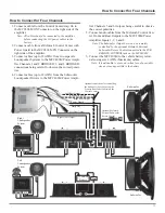
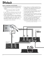
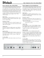
In the 4 Channel Operating Mode channel pairs of (1 and
2) and (3 and 4) are bridged to provide 200 watts each.
Channels 5 and 6 are driven independently for 100 watts
output for each channel. Refer to figures 8 and 9, along
with page 11 of this Owner’s Manual.
Input Source
Set the Channel 3-4 INPUT SOURCE Switch to the 3, 4
and the Channel 5-6 INPUT SOURCE Switch to the 5, 6
position for 4 Channel Mode.
Sensitivity Controls
The Sensitivity Controls (1, 3, 5 and 6) allow setting the
input level of the amplifier channels to provide an ideal
match for the signal source being used.
Note: Set CH2 and CH4 SENSITIVITY Controls to the
maximum counterclockwise position.
Output Mode
Set CHANNELS 1-2 and 3-4 OUTPUT MODE Switches
to the BRIDGED position. Set CHANNELS 5-6 OUTPUT
MODE Switch to the STEREO position. This will config-
ure the amplifier for four channel operation.
High Pass Filter
Set the Channels 1-2 and 3-4 High Pass Filters’ FRE-
QUENCY Control to 100 and the MULTIPLIER Switch to
X1. Set the channel 5-6 High Pass Filter Frequency Control
to 50 and the MULTIPLIER Switch to X.1. This will send
frequencies above 100Hz to the upper range speakers for
channels 1 thru 4 and roll-off frequencies below 5Hz for
channels 5-6.
Low Pass Filter
Set the Channel 3-4 low pass filter to OUT. Set the Chan-
nel 5-6 Low Pass Filter FREQUENCY Control to 100 and
the MULTIPLIER Switch to X1. This will roll-off frequen-
cies above 100Hz for channels 5-6.
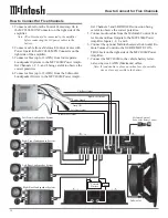
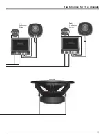
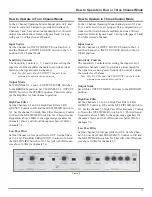
In the 3 Channel Operating Mode channel pairs of (1 and
2), (3 and 4) and (5-6) are bridged. This configuration pro-
vides two 200 watt channel amplifiers and one 400 watt
amplifier. Refer to figures 8 and 9, along with pages 12 and
13 of this Owner’s Manual.
Input Source
Set the Channel 3-4 INPUT SOURCE Switch to the 3, 4
and the Channel 5-6 INPUT SOURCE Switch to the 1-4
(SUB) position.
Sensitivity Controls
The Sensitivity Controls allow setting the input level of
amplifier channels 1 and 3 to provide an ideal match for
the signal source being used. Sensitivity Control 5 adjusts
the woofer level balance.
Note: Set CH2, CH4 and CH6 SENSITIVITY Controls to the
maximum counterclockwise position.
Output Mode
Set all three OUTPUT MODE Switches to the BRIDGED
position.
High Pass Filter
Set the Channels 1-2 and 3-4 High Pass Filters’ FRE-
QUENCY Control to 100 and the MULTIPLIER Switch to
X1. Set the channel 5-6 High Pass Filter Frequency Control
to 50 and the MULTIPLIER Switch to X.1. This will send
frequencies above 100Hz to the upper range speakers for
channels 1 thru 4 and roll-off frequencies below 5Hz for
channels 5-6.
Low Pass Filter
Set the Channel 3-4 low pass filter to OUT. Set the Chan-
nel 5-6 Low Pass Filter FREQUENCY Control to 100 and
the MULTIPLIER Switch to X1. This will roll-off frequen-
cies above 100Hz for channels 5-6.
Figure 9
Summary of Contents for MCC406M
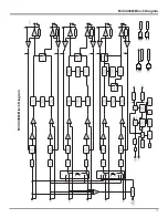
Page 19: ...19 MCC406M Block Diagram MCC406M Block Diagram ...
Page 20: ...20 ...
Page 21: ...21 Notes ...

