Care
Point:
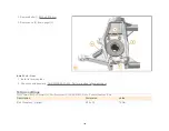
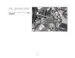
Use ball joint splitter to separate.
1.
2.
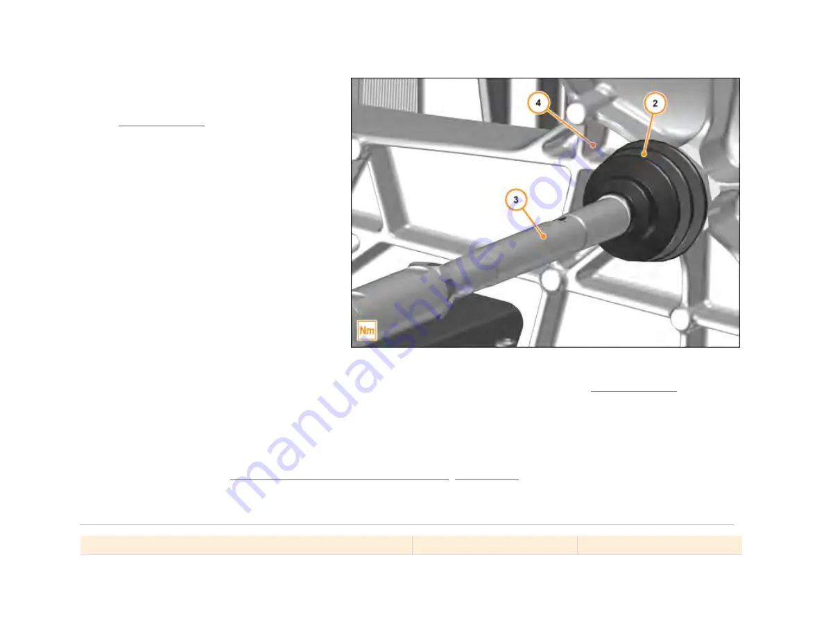
Pull back dust cover (2).
3.
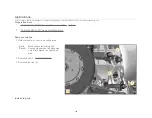
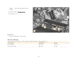
Unscrew tie rod (3) from aluminium subframe
(4). M16 x 1.5 80 Nm
4.
Remove tie rod (3).
Install tie rod - Rear
Care
Point:
1.
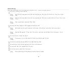
Install components in reverse order.
2.
Perform geometry check
3.
Check chassis geometry AA-RM-03B03-01-002 - Perform a wheel alignment check .
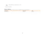
Torque settings
FG03 Chassis / B02 Rear Suspension / Rear Suspension LH / AA-RM-03B02-01-007 - Remove/install tie rod - Rear
Description
Dimension
Value
Nut Tie rod - Upright
M12
70 Nm
Bolt Tie rod - Aluminium subframe
M16 x 1.5
80 Nm
Bolt Tie rod - Aluminium subframe
M16 x 1.5
80 Nm
131
Summary of Contents for MP4-12C
Page 1: ......
Page 35: ...5 Disc Cross Drilled Hole Chip on disc Do not renew disc 1 34 ...
Page 52: ...2 Detach union nut 2 M10 17 Nm 3 Loosen nut 3 4 Remove front brake hose 4 51 ...
Page 69: ...2 Detach union nut 2 M10 17 Nm 3 Loosen nut 3 4 Remove rear brake hose 4 68 ...
Page 98: ...Description Dimension Value Bolt Floor panel tunnel M6 x 16 10 Nm 97 ...
Page 104: ...1 Remove bolts 1 M6 x 20 4 Nm 2 Remove tyre spoilers 2 Remove front guide vanes 103 ...
Page 105: ...1 Remove screws 1 M6 x 16 6 Nm 2 Remove front guide vanes 2 Remove rear guide vanes 104 ...
Page 125: ...Description Dimension Value Track rod steering rack M14 30 Nm 124 ...
Page 194: ...4 Remove bolts 2 M6 x 20 8 Nm 5 Remove bolts 3 M6 x 16 8 Nm 193 ...
Page 195: ...5 Remove bolts 3 M6 x 16 8 Nm 6 Remove bolts 4 M6 x 16 8 Nm 194 ...
Page 196: ...6 Remove bolts 4 M6 x 16 8 Nm 7 Remove bodyside lower rear arrows 195 ...
Page 203: ...Description Dimension Value Clamp ISG to Throttle M6 5 Nm 202 ...


