background image

Description

Dimension

Value

Nut Tie rod - Upright

M12

70 Nm

Bolt Tie rod - Aluminium subframe

M16 x 1.5

80 Nm

Bolt Tie rod - Aluminium subframe

M16 x 1.5

80 Nm

132

Summary of Contents for MP4-12C

Page 1: ......

Page 2: ... 2 4 5 7 9 13 15 17 37 41 46 49 54 58 62 66 71 74 77 80 88 91 93 96 98 102 106 108 111 114 118 122 125 128 130 133 137 139 Suspension Z Bar Suspension Wheel Alignment Wheel Liner Rear Engine Oil Change Turbo Oil Return Hose Air Filter Replace Coolant Drain Fluid Clutch Drain Fluid Clutch Replace Filter Floor Diffuser Floor Panel Transmission Drain Fluid Transmission Replace Filter Fuel Filter Repl...

Page 3: ...uel Filler AA RM 02A04 03 001 Remove install fender cover Inner Remove fender cover Inner Care Point Work carefully to prevent paint damage 1 Open luggage compartment lid Care Point Start pulling up cover fender from rear edge 2 Remove fender inner 1 Install fender cover Inner 2 ...

Page 4: ...Care Point Start with front edge because of firtree clip and ensure alignment with hole 1 Install components in reverse order 3 ...

Page 5: ...es out adjustment whilst second technician operates headlamp alignment equipment Adjust headlamp Care Point Inboard adjuster for vertical adjustment outboard adjuster for horizontal adjustment 1 Use adjuster for vertical adjustment 1 2 Use adjuster for horizontal adjustment 2 Care Point Height equals 62cm with inclination of 1 2 Ensure dipped beams are 0 1 of 1 2 3 Carry out adjustment to country ...

Page 6: ...A RM 02A02 03 004 Remove install luggage bin Rear Remove luggage bin Rear 1 Open luggage compartment lid 2 Remove contents of luggage bin 3 Remove luggage bin finisher 4 Remove bolts 1 M6 x 16 4 Nm 5 Remove fixings 2 6 Remove luggage bin 3 Install luggage bin Rear 1 Install components in reverse order 5 ...

Page 7: ...ttings FG02 Body Systems A02 Exterior Trim Lighting Wipers Luggage Cell Ducts Wheelarch Liners AA RM 02A02 03 004 Remove install luggage bin Rear Description Dimension Value Bolt luggage bin Rear M6 x 16 4 Nm 6 ...

Page 8: ...required in this event If hydraulic fluid is swallowed this can lead to poisoning symptoms such as headache dizziness nausea vomiting diarrhoea cramps and unconsciousness Always wear skin protection cream protective gloves and safety glasses when working on a potentially pressurised system Fill bleed fluid Steering system 1 Open bonnet 2 Remove power steering reservoir cap 1 3 Fill up power steeri...

Page 9: ...Care Point Ensure the car is on the ground 4 Turn steering wheel from lock A to lock B three times 5 Check power steering fluid and fill up if necessary 6 Install power steering reservoir cap 8 ...

Page 10: ... with the throttle pedal fully released Neutral gear selected and the foot brake applied use left foot If any of these conditions are not met a warning message will be displayed on the instrument cluster Care Point The foot brake must be applied for the entire duration of the oil level check Care Point The oil level status can be viewed in the Vehicle information section in the left hand instrumen...

Page 11: ...of 70 C measured via the oil level sensor Care Point The oil level check will limit the rpm input to 2000rpm once the test has begun but the throttle must be applied for the duration of the oil level check If the throttle pedal is released and the engine speed drops below 2000 rpm during the oil level check then the oil level check will abort and return you to the apply throttle screen The 40 seco...

Page 12: ...o not continue to test the system This may lead to aeration of the oil and return a false value To end the oil level check release the throttle and abort back to the vehicle info menu 5 When the timer has reached 0 Care Point When the timer has reached 0 Care Point The engine must be switched off and the instrument cluster must be returned to the vehicle info menu before carrying out an oil top up...

Page 13: ...luster must be returned to the vehicle info menu before carrying out an oil top up and retest 6 If the engine oil is below target level top up with the correct quantity of oil in accordance to the graphic opposite Approximately 0 50 litres is required to raise the level from minimum to target level 7 Carry out the oil level check process to ensure the level is correct 8 Top up as required by repea...

Page 14: ...rt plates on the lifting platform support points at the same height Raise the vehicle a few inches first wheels are still touching the ground and check the position and fit of the support plates and lift points before raising the vehicle to the full lifted position Do not raise the vehicle off the lifting platform plates when components are being supported Centre the vehicle lengthwise and crosswi...

Page 15: ... Ensure vehicle is in correct orientation to allow door opening Care Point Ensure lifting arm pads do not obstruct removal of floor panels 1 Carefully position lifting arms on jacking points 1 2 Raise vehicle 14 ...

Page 16: ...eels Tyres Wheel Assembly AA RM 03B03 01 001 Remove install wheel Preparation work 1 AA RM 02A04 04 007 Secure lift vehicle on lifting platform Remove wheel 1 Remove wheel bolts in sequence A E 130 Nm 2 Remove wheel 1 Install wheel 15 ...

Page 17: ...l components in reverse order 2 Check tyre pressure and correct if necessary Care Point Once vehicle is on ground 3 Apply pressure to top of wheel towards vehicle If excessive inward movement of wheel is present the upper ball joint has failed The wishbone will require replacing Torque settings FG03 Chassis B03 Wheels Tyres Wheel Assembly AA RM 03B03 01 001 Remove install wheel Description Dimensi...

Page 18: ... 03C01 03 002 Remove install brake disc rear Cleaning Checking carbon ceramic brake disc CCM Iron brake disc Fe 1 When carrying out this procedure the following safety equipment must be worn dust mask sleeve protection and plastic gloves Care Point Only pick up the disc from the bell housing Do not handle from the ventilation channels Care Point Cleaning of the discs pads and cross drilled holes m...

Page 19: ...c CCM Iron brake discs Fe and pads 1 Clean Iron brake discs Fe and pads Care Point Do not machine cross drilled holes Care Point Do not flare cross drilled holes Care Point Do not carry out any form of grinding on the disc Care Point Cleaning of the discs pads and cross drilled holes must be carried out before replacement Care Point Only use screwdriver punch with a max diameter of 5mm to clean cr...

Page 20: ...1 Use a screwdriver punch A to initially clear the cross drilled holes of composite build up 2 Once all holes are cleared use a pressurised air gun B to clean out the final remnants of build up 19 ...

Page 21: ...2 Once all holes are cleared use a pressurised air gun B to clean out the final remnants of build up Disc replacement required 20 ...

Page 22: ...ptable condition 3 There has been an excessive drop in braking performance 4 The disc has been subjected to accidental damage 5 The disc face has been damaged due to 100 pad wear metal to disc contact 6 If the vehicle has been involved in an accident where a wheel face has been impacted For points 1 2 and 3 these will occur to the brake discs through normal use over time Care Point Please note tha...

Page 23: ...r edge 3 disc must be replaced Care Point Differential wear must not exceed 0 5mm side to side 4 Minimum disc thickness are 30mm Front 28mm Rear Care Point Please note CCM discs do not lose performance once the braking surface shows indications of being worn so may still be used On CCM discs it is common for the braking surface to change visually during use The change is caused by temperature vari...

Page 24: ... the pad 2 Please note that this does not affect the performance of the disc 1 Care Point Discs must be replaced if pad wear has reached 100 If pads have reached 100 wear there is a high chance that the back plate has come into contact with the braking face visible mark will be present 2 Discs 1 must be replaced immediately if this circumstance has occurred due to contamination of the disc 1 23 ...

Page 25: ...aused when the fibres within the CCM experience a high level of thermal input This then causes the fibres to oxidize changing the surface appearance This condition mainly occurs after extreme use such as racing The oxidisation level is calculated by disc porosity and surface roughness Areas that are mainly affected by the change in the braking surface are an increase in pad wear decreased NVH and ...

Page 26: ...e oxidisation level is calculated by disc porosity and surface roughness Areas that are mainly affected by the change in the braking surface are an increase in pad wear decreased NVH and a decrease in disc performance If the level of oxidisation experienced is very high the disc must be replaced See below for examples of the different levels of oxidisation experienced 3 Disc surface 1 Immediately ...

Page 27: ...for examples of the different levels of oxidisation experienced 3 Disc surface 1 Immediately after bedding Do not renew 4 Disc surface 1 200 km racing on track Do not renew 5 Disc surface 1 500 km racing on track Do not renew 26 ...

Page 28: ...5 Disc surface 1 500 km racing on track Do not renew 6 Disc surface 1 1000 km hard racing on track Check disc weight 27 ...

Page 29: ...6 Disc surface 1 1000 km hard racing on track Check disc weight 7 Disc surface 1 1500 2000 km racing on track Renew disc end of disc life 28 ...

Page 30: ... precision gauge with a tolerance of 0 1mm Care Point If disc is damaged outside of specified figures along the edge of the braking surface disc must be renewed Care Point Any damage on the edge of the braking surface will not affect the disc weight due to the material density Checking CCM disc Damage control specifications 29 ...

Page 31: ...idth E Maximum allowed 4 mm Depth D Maximum allowed 3 mm Length F Maximum allowed 20 mm Chips Maximum allowed 3 per disc Projected area Maximum area allowed 40 mm Care Point See below examples of damage that may occur to a CCM disc 1 and the relevant action you should employ 2 Disc Edge Chip on used disc Renew disc 1 30 ...

Page 32: ...int See below examples of damage that may occur to a CCM disc 1 and the relevant action you should employ 2 Disc Edge Chip on used disc Renew disc 1 3 Disc Cross Drilled Hole Chip on used disc Renew disc 1 31 ...

Page 33: ...3 Disc Cross Drilled Hole Chip on used disc Renew disc 1 4 Disc Edge Chip on disc Do not renew disc 1 32 ...

Page 34: ...4 Disc Edge Chip on disc Do not renew disc 1 5 Disc Cross Drilled Hole Chip on disc Do not renew disc 1 33 ...

Page 35: ...5 Disc Cross Drilled Hole Chip on disc Do not renew disc 1 34 ...

Page 36: ...ar experienced To get this information the disc must be weighed Before weighing the disc it must be thoroughly cleaned including all cross drilled holes The disc must be dry and free of moisture due to the porous nature of the CCM material Suitable and calibrated weighing scales must be used when carrying out this procedure Due to the fibres in the CCM disc oxidizing when subjected to extreme ther...

Page 37: ...d weight against marked minimum weight on disc bell G 4 To measure the estimated disc life using data recorded for mileage and residual disc weight please use the following formula 1st Service mileage ODO1 15000km Residual weight R1 118g 2nd Service mileage ODO2 25000km Residual weight R2 67g Wear estimate WE R2 R1 ODO2 ODO1 WE 67 118 25000 15000 WE 51 10000 WE 0 0051 Estimated disc life EDL ODO2 ...

Page 38: ...ke System Brake Discs Calipers Front AA RM 03C01 01 001 Remove install brake pads Front Preparation work 1 AA RM 02A04 04 007 Secure lift vehicle on lifting platform 2 AA RM 03B03 01 001 Remove install wheels Remove brake pads Front 37 ...

Page 39: ...d protective clothing such as rubber gloves Ensure that brake fluid is only accessible to authorized personnel Store brake fluid in original containers only Only store brake fluid in suitable appropriately marked containers Never put brake fluid in beverage containers 1 Release brake fluid reservoir cap 2 Disconnect brake pad wear indicator electrical connector 3 Remove brake pad securing pins 1 4...

Page 40: ... is increased due to an impaired braking effect Press the brake pedal several times to build up pressure in the brake system after finishing work on the braking system s hydraulics area and before starting the vehicle Hold the brake pedal in a pressed down position for approximately 30 s once pressure has been built up in the brake system the pressure in the brake system must not drop during this ...

Page 41: ...ng brake fluid can cause symptoms of poisoning such as headaches dizziness stomach pains vomiting diarrhoea cramps and unconsciousness A dose of more than 100 cm3 can have fatal consequences Contact with brake fluid can cause serious skin damage to unprotected skin Wear safety glasses and protective clothing such as rubber gloves Ensure that brake fluid is only accessible to authorized personnel S...

Page 42: ... and unconsciousness A dose of more than 100 cm3 can have fatal consequences Contact with brake fluid can cause serious skin damage to unprotected skin Wear safety glasses and protective clothing such as rubber gloves Ensure that brake fluid is only accessible to authorized personnel Store brake fluid in original containers only Only store brake fluid in suitable appropriately marked containers Ne...

Page 43: ... to avoid contamination Care Point Collect the brake fluid that emerges in a suitable container Care Point Close off the brake line with a suitable plug 1 Remove bolt 1 M5 x 12 5 Nm Care Point Replace Copper washers 2 Remove banjo bolt 2 M10 42 Nm 3 Remove bolts 3 M12 x 85 93 Nm 4 Remove caliper 4 Detach brake caliper Front 42 ...

Page 44: ...ns are clean and free from dirt and debris to avoid contamination Care Point Do not let caliper hang on brake hose 1 Remove bolts 3 M12 x 85 93 Nm 2 Detach caliper 4 and hang in suitable location with cable tie Install brake caliper Front 43 ...

Page 45: ...time Care Point Replace O Ring seals and copper washers Care Point Ensure brake components are clean and free from dirt and debris Care Point Always renew bolts Care Point Ensure that the pad wear sensor and brake hose are secured with P clips positioned perpendicular to the brake disc Care Point Where fitted clean and apply loctite to disc cooling duct bolt Loctite 243 1 Install components in rev...

Page 46: ...Description Dimension Value Bolt cooling duct brake caliper M5 x 12 5 Nm Banjo bolt Brake hose Caliper M10 42 Nm Bolt Caliper M12 x 85 93 Nm Bolt Caliper M12 x 85 93 Nm 45 ...

Page 47: ...all brake disc Front Preparation work 1 AA RM 02A04 04 007 Secure lift vehicle on lifting platform 2 AA RM 03B03 01 001 Remove install wheels 3 AA RM 03C01 01 002 Remove install brake caliper Front Remove brake disc Front 1 Remove bolt 1 M6 x 15 10 Nm 2 Remove brake disc 2 Install brake disc Front 46 ...

Page 48: ... in original containers only Only store brake fluid in suitable appropriately marked containers Never put brake fluid in beverage containers 3 Check brake fluid level and refill if necessary AA RM 03C01 01 005 Fill bleed fluid Brake system WARNING Risk of accident due to lack of braking effect When the brakes are used for the first time after any work was performed on the braking system s hydrauli...

Page 49: ...Torque settings FG03 Chassis C01 Brake System Brake Discs Calipers Front AA RM 03C01 01 003 Remove Install brake disc Front Description Dimension Value Bolt Brake disc Hub M6 x 15 10 Nm 48 ...

Page 50: ...isoning such as headaches dizziness stomach pains vomiting diarrhoea cramps and unconsciousness A dose of more than 100 cm3 can have fatal consequences Contact with brake fluid can cause serious skin damage to unprotected skin Wear safety glasses and protective clothing such as rubber gloves Ensure that brake fluid is only accessible to authorized personnel Store brake fluid in original containers...

Page 51: ...Care Point Use a suitable container to catch the excess fluid Care Point Close off the caliper with a suitable plug 1 Remove banjo bolt 1 and Copper washer M10 42 Nm 2 Detach union nut 2 M10 17 Nm 50 ...

Page 52: ...2 Detach union nut 2 M10 17 Nm 3 Loosen nut 3 4 Remove front brake hose 4 51 ...

Page 53: ...ean area around union Care Point Replace Copper washers 1 Install components in reverse order 2 Bleed braking system AA RM 03C01 01 005 Fill bleed fluid Brake system Torque settings FG03 Chassis C01 Brake System Brake Front Pipes AA RM 03C01 02 001 Remove Install brake hose Front 52 ...

Page 54: ...Description Dimension Value Banjo bolt Brake hose Calliper M10 42 Nm Union nut Brake pipe Brake hose M10 17 Nm 53 ...

Page 55: ...ake System Brake Discs Calipers Rear AA RM 03C01 03 003 Remove install brake pads Rear Preparation work 1 AA RM 02A04 04 007 Secure lift vehicle on lifting platform 2 AA RM 03B03 01 001 Remove Install wheels Remove brake pads Rear 54 ...

Page 56: ...fety glasses and protective clothing such as rubber gloves Ensure that brake fluid is only accessible to authorized personnel Store brake fluid in original containers only Only store brake fluid in suitable appropriately marked containers Never put brake fluid in beverage containers 1 Release brake fluid reservoir cap 2 Disconnect brake pad wear indicator electrical connector 3 Remove brake pad se...

Page 57: ... times to build up pressure in the brake system after finishing work on the braking system s hydraulics area and before starting the vehicle Hold the brake pedal in a pressed down position for approximately 30 s once pressure has been built up in the brake system the pressure in the brake system must not drop during this time Care Point Ensure brake components are clean and free from dirt and debr...

Page 58: ... and injury when handling brake fluid Swallowing brake fluid can cause symptoms of poisoning such as headaches dizziness stomach pains vomiting diarrhoea cramps and unconsciousness A dose of more than 100 cm3 can have fatal consequences Contact with brake fluid can cause serious skin damage to unprotected skin Wear safety glasses and protective clothing such as rubber gloves Ensure that brake flui...

Page 59: ...nd unconsciousness A dose of more than 100 cm3 can have fatal consequences Contact with brake fluid can cause serious skin damage to unprotected skin Wear safety glasses and protective clothing such as rubber gloves Ensure that brake fluid is only accessible to authorized personnel Store brake fluid in original containers only Only store brake fluid in suitable appropriately marked containers Neve...

Page 60: ...oid contamination Care Point Collect the brake fluid that emerges in a suitable container Care Point Close off the brake line with a suitable plug Care Point Replace Copper washers 1 Remove banjo bolt 1 M10 42 Nm 2 Remove bolts 2 Carbon Ceramic CCM M12 x 85 93 Nm Iron Fe M12 x 66 70 Nm 3 Remove caliper 3 Detach brake caliper Rear 59 ...

Page 61: ...d debris to avoid contamination Care Point Do not let caliper hang on brake hose 1 Remove bolts 2 M12 x 85 93 Nm Care Point Ensure the caliper in a suitable position with cable ties 2 Detach caliper and hang in suitable location with cable tie 3 Install brake caliper Rear 60 ...

Page 62: ... has been built up in the brake system the pressure in the brake system must not drop during this time Care Point Replace O Ring seals and copper washers Care Point Ensure brake components are clean and free from dirt and debris Care Point Always renew bolts 1 Install components in reverse order 2 Bleed brake system if necessary AA RM 03C01 01 005 Fill bleed fluid Brake system Torque settings FG03...

Page 63: ... brake 4 AA RM 03C01 03 001 Remove install brake caliper rear Remove brake disc Rear Care Point The Electronic parking brake in inoperative when this sequence is carried out Care Point Before mechanical work on Parking Brake components you must set calipers in fully open position 1 Connect McLaren Diagnostic System proceed to Diagnostic Toolbox within Electronic parking brake EPB 2 Access Sequence...

Page 64: ... brake pads are correctly seated WARNING Risk of poisoning and injury when handling brake fluid Swallowing brake fluid can cause symptoms of poisoning such as headaches dizziness stomach pains vomiting diarrhoea cramps and unconsciousness A dose of more than 100 cm3 can have fatal consequences Contact with brake fluid can cause serious skin damage to unprotected skin Wear safety glasses and protec...

Page 65: ...uild up pressure in the brake system after finishing work on the braking system s hydraulics area and before starting the vehicle Hold the brake pedal in a pressed down position for approximately 30 s once pressure has been built up in the brake system the pressure in the brake system must not drop during this time 4 If new brake pads discs have been fitted bed in the brakes AA RM 03C01 01 004 Bed...

Page 66: ...his sequence 5 Connect McLaren Diagnostic System proceed to Diagnostic Toolbox within Electronic parking brake EPB 6 Access Sequences section 7 Carry out EBP caliper Closed 8 Carry out EBP Assembly Check Torque settings FG03 Chassis C01 Brake System Brake Discs Calipers Rear AA RM 03C01 03 002 Remove install brake disc Rear Description Dimension Value Bolt Brake disc Hub M6 x 15 10 Nm 65 ...

Page 67: ...isoning such as headaches dizziness stomach pains vomiting diarrhoea cramps and unconsciousness A dose of more than 100 cm3 can have fatal consequences Contact with brake fluid can cause serious skin damage to unprotected skin Wear safety glasses and protective clothing such as rubber gloves Ensure that brake fluid is only accessible to authorized personnel Store brake fluid in original containers...

Page 68: ...Care Point Use a suitable container to catch the excess fluid Care Point Close off the caliper with a suitable plug 1 Remove banjo bolt 1 and copper washer M10 42 Nm 2 Detach union nut 2 M10 17 Nm 67 ...

Page 69: ...2 Detach union nut 2 M10 17 Nm 3 Loosen nut 3 4 Remove rear brake hose 4 68 ...

Page 70: ...ean area around union Care Point Replace copper washer 1 Install components in reverse order 2 Bleed braking system AA RM 03C01 01 005 Fill bleed fluid Brake system Torque settings FG03 Chassis C01 Brake System Brake Rear Pipes AA RM 03C01 04 001 Remove install brake hose Rear 69 ...

Page 71: ...Description Dimension Value Banjo bolt Brake hose Calliper M10 42 Nm Union nut Brake pipe Brake hose M10 17 Nm 70 ...

Page 72: ...arking brake Care Point The electronic parking brake is inoperative when this sequence is carried out Care Point Before mechanical work on Parking Brake components you must set callipers in fully open position 1 Connect McLaren Diagnostic System proceed to Diagnostic Toolbox within Electronic parking brake EPB 2 Access Sequences section 3 Carry out EPB Calliper Open 4 Remove pin securing clips 1 5...

Page 73: ...tronic parking brake EPB 2 Access Sequences section 3 Carry out EPB Calliper Open 4 Remove pin securing clips 1 5 Remove pad pins 2 and anti rattle clip 3 6 Remove electronic parking brake pads Install pads Electronic parking brake 72 ...

Page 74: ... unauthorised access when parts are in motion Never touch the mechanism of a component while it is being actuated Choose a test cable of sufficient length Care Point After mechanical work on Parking Brake components you must set callipers in fully closed position Care Point The Parking Brake will be applied ensure it is safe to proceed with this sequence 3 Connect McLaren Diagnostic System proceed...

Page 75: ...Care Point The electronic parking brake is inoperative when this sequence is carried out Care Point Before mechanical work on Parking Brake components you must set callipers in fully open position 1 Connect McLaren Diagnostic System proceed to Diagnostic Toolbox within Electronic parking brake EPB 2 Access Sequences section 3 Carry out EPB Calliper Open 4 Disconnect electronic parking brake actuat...

Page 76: ...e EPB 2 Access Sequences section 3 Carry out EPB Calliper Open 4 Disconnect electronic parking brake actuator electrical connector 1 5 Remove bolts 2 M6 x 12 11 Nm 6 Remove electronic parking brake actuator 3 Install electronic parking brake actuator 75 ...

Page 77: ...sm of a component while it is being actuated Choose a test cable of sufficient length Care Point After mechanical work on Parking Brake components you must set callipers in fully closed position Care Point The Parking Brake will be applied ensure it is safe to proceed with this sequence 2 Connect McLaren Diagnostic System proceed to Diagnostic Toolbox within Electronic parking brake EPB 3 Access S...

Page 78: ...k of injury from moving parts When working on components which can be moved either by hand by means of electric motors or hydraulically pneumatically via linkage serious injuries can occur to body parts being trapped crushed or severed Monitor hazard area Secure area against unauthorised access when parts are in motion Never touch the mechanism of a component while it is being actuated Choose a te...

Page 79: ...ren Diagnostic System proceed to Diagnostic Toolbox within Electronic parking brake EPB 2 Access Sequences section 3 Carry out EPB caliper Open Care Point Clean electrical connector before disconnection Do not use any hand tools to disconnect electrical connector 4 Disconnect electronic parking brake actuator electrical connector 2 5 Remove bolts 3 M10 x 85 33 Nm 6 Remove electronic parking brake ...

Page 80: ... on Parking Brake components you must set calipers in fully closed position Care Point The Parking Brake will be applied ensure it is safe to proceed with this sequence 2 Connect McLaren Diagnostic System proceed to Diagnostic Toolbox within Electronic parking brake EPB 3 Access Sequences section 4 Carry out EPB caliper Closed 5 Carry out EPB Assembly Check Torque settings FG03 Chassis C02 Parking...

Page 81: ...e Hold the brake pedal in a pressed down position for approximately 30 s once pressure has been built up in the brake system the pressure in the brake system must not drop during this time WARNING Risk of poisoning and injury when handling brake fluid Swallowing brake fluid can cause symptoms of poisoning such as headaches dizziness stomach pains vomiting diarrhoea cramps and unconsciousness A dos...

Page 82: ...below steps reference the procedure stored on the MDS tool 1 Connect MDS to vehicle 2 Open brake reservoir cap 1 Care Point Tool must deliver 2 2 bar pressure 2 and have a minimum of 2 Litres of brake fluid to carry out procedure correctly 3 Connect pressure bleeding tool 81 ...

Page 83: ...eding tool Care Point Pump the brake pedal during each phase of the brake bleeding procedure Care Point Pedal pump frequency 3 seconds applied to 0 5 seconds released 4 Fit bleed bottle to rear left calliper and open both inner and outer bleed screws 3 4 M10 17 Nm 5 Pump pedal until no air is present 6 Close bleed screws on rear left calliper 3 4 82 ...

Page 84: ...per and open both inner and outer bleed screws 3 4 M10 17 Nm 5 Pump pedal until no air is present 6 Close bleed screws on rear left calliper 3 4 Care Point Pedal pump frequency 3 seconds applied to 0 5 seconds released 7 Fit bleed bottle to front left calliper and open both inner and outer bleed screws 5 6 8 Pump pedal until no air is present 9 Close bleed screws on front left calliper 5 6 83 ...

Page 85: ... screws 5 6 8 Pump pedal until no air is present 9 Close bleed screws on front left calliper 5 6 Care Point Pedal pump frequency 3 seconds applied to 0 5 seconds released 10 Fit bleed bottle to front right calliper and open both inner and outer bleed screws 7 8 11 Pump pedal until no air is present 12 Close bleed screws on front right calliper 7 8 84 ...

Page 86: ...econds applied to 0 5 seconds released 13 Fit bleed bottle to rear right calliper and open both inner and outer bleed screws 9 10 14 Pump pedal until no air is present 15 Close bleed screws on rear right calliper 9 10 Care Point If process needs to be repeated allow the system to rest for a minimum of 5 minutes to prevent damage being caused to the braking system 16 Disconnect pressure bleeding to...

Page 87: ...is present 15 Close bleed screws on rear right calliper 9 10 Care Point If process needs to be repeated allow the system to rest for a minimum of 5 minutes to prevent damage being caused to the braking system 16 Disconnect pressure bleeding tool 17 Check brake fluid level and fill to the correct level Pentosin 5 1 or Mobil 1 5 1 18 Close brake fluid reservoir cap 1 19 Check functionality 86 ...

Page 88: ...he correct level Pentosin 5 1 or Mobil 1 5 1 18 Close brake fluid reservoir cap 1 19 Check functionality Torque settings FG03 Chassis C01 Brake System Brake Discs Calipers Front AA RM 03C01 01 005 Fill bleed fluid Brake system Description Dimension Value Bleed Screw M10 17 Nm 87 ...

Page 89: ...performance of the brakes can be decreased Follow the sequence of the procedure Care Point New pads and discs must be bedded in if not pad disc performance will be decreased Care Point The brakes should be cold Less than 40 C before carrying out this procedure if possible only use light brake applications whilst driving to the location Bedding new brake pads discs carbon ceramic material CCM 88 ...

Page 90: ... reached should be 700 C at the end of the tenth stop The cycle time is around 20 seconds between brake applications 6 Drive 4 km 2 5 miles to allow the brakes to cool 7 Use Full ABS max pedal effort and slow the vehicle three times from 100 km h 62 mph to 0 km h 0 mph The Max starting disc temperature should be 40 C Increase the speed normally after you have slowed down Care Point The cool down p...

Page 91: ...es from 100 km h 62 mph to 0 km h 0 mph at 0 7g Allow 60 seconds 1 minute between each application 6 Slow the vehicle five times from 100 km h 62 mph to 0 km h 0 mph at 0 7g Allow 30 seconds between each application 7 Drive 4 km 2 5 miles to allow the brakes to cool 8 Slow the vehicle five times from 100 km h 62 mph to 0 km h 0 mph at 0 7g Accelerate the vehicle as quickly as possible between stop...

Page 92: ...el Engine fuel tank Preparation work 1 AA RM 02A04 04 007 Secure lift vehicle on lifting platform Remove floor panel Engine fuel tank Care Point Two technicians required 1 Remove bolts 1 and washers M6 x 20 10 Nm 2 Remove bolts 2 M6 x 12 6 Nm 3 Remove bolts 3 M6 x 16 10 Nm 4 Remove engine fuel tank floor panel 4 91 ...

Page 93: ... in reverse order Torque settings FG02 Body Systems A04 Panels Glazing Paint Floors Diffuser AA RM 02A04 04 001 Remove install floor panel Engine fuel tank Description Dimension Value Bolt Floor panel engine fuel tank M6 x 20 10 Nm Bolt Floor panel engine fuel tank M6 x 12 6 Nm Bolt Floor panel engine fuel tank M6 x 16 10 Nm 92 ...

Page 94: ...move install floor panel Front Up to MY14 Preparation work 1 AA RM 02A04 04 007 Secure lift vehicle on lifting platform Remove floor panel Front Up to MY14 1 Remove bolts 1 M6 x 20 2 Nm 2 Remove bolts 2 M6 x 20 6 Nm 3 Remove tyre spoiler 3 4 Remove bolts 5 M6 x 20 4 Nm 5 Detach floor panel 4 93 ...

Page 95: ...4 Remove bolts 5 M6 x 20 4 Nm 5 Detach floor panel 4 Care Point With the aid of another technican support the floor panel 6 Remove bolts 6 M6 x 20 4 Nm 7 Remove floor panel 94 ...

Page 96: ...Y14 1 Install components in reverse order Torque settings FG02 Body Systems A04 Panels Glazing Paint Floors Diffuser AA RM 02A04 04 002 Remove install floor panel Front Up to MY14 Description Dimension Value Bolt tyre spoiler front panel M6 x 20 2 Nm Bolt Floor panel M6 x 20 6 Nm Bolt Front floor panel M6 x 20 4 Nm Bolt Front floor panel M6 x 20 4 Nm 95 ...

Page 97: ... RM 02A04 04 007 Secure lift vehicle on lifting platform Remove floor panel Tunnel 1 Remove bolts M6 x 16 2 M6 x 16 10 Nm 2 Remove tunnel floor panel 1 Install floor panel Tunnel 1 Install components in reverse order Torque settings FG02 Body Systems A04 Panels Glazing Paint Floors Diffuser AA RM 02A04 04 003 Remove install floor panel Tunnel 96 ...

Page 98: ...Description Dimension Value Bolt Floor panel tunnel M6 x 16 10 Nm 97 ...

Page 99: ...emove install floor panel Engine fuel tank Care Point Ensure that the fuel filler drain hose does not become detached from the fuel filler bowl whilst carrying out this procedure Care Point The fuel filler drain hose will only be attached to the left hand floor panel rear lower extension Care Point Only carry out steps 1 and 2 if you are replacing both or the left hand only floor panel rear lower ...

Page 100: ...1 Remove jubilee clip 2 Detach hose 3 Remove bolt 1 M 5 Nm 4 Remove bolts 2 M6 x 20 2 Nm 5 Remove bolts 3 4 2 x 16 2 Nm 6 Remove floor panel Rear lower extension 4 99 ...

Page 101: ...before installing all pre work components Install floor panel Rear lower extension 1 Install components in reverse order Torque settings FG02 Body Systems A04 Panels Glazing Paint Floors Diffuser AA RM 02A04 04 005 Remove install floor panel Rear lower extension Description Dimension Value Bolt Rear lower extension Wheel arch liner M 5 Nm Bolt tyre spoiler front panel M6 x 20 2 Nm Screw tyre spoil...

Page 102: ...Description Dimension Value Bolt Rear lower extension Wheel arch liner M 5 Nm Bolt tyre spoiler front panel M6 x 20 2 Nm Screw tyre spoiler front panel 4 2 x 16 2 Nm 101 ...

Page 103: ...l tyre spoilers front guide vanes rear guide vanes Preparation work 1 AA RM 02A04 04 007 Secure lift vehicle on lifting platform Remove tyre spoilers Up to MY14 1 Remove screw 1 2 Remove bolt 2 M6 x 20 2 Nm 3 Remove screws 3 4 2 x 16 2 Nm 4 Remove tyre spoiler 4 Remove tyre spoilers From MY15 onwards 102 ...

Page 104: ...1 Remove bolts 1 M6 x 20 4 Nm 2 Remove tyre spoilers 2 Remove front guide vanes 103 ...

Page 105: ...1 Remove screws 1 M6 x 16 6 Nm 2 Remove front guide vanes 2 Remove rear guide vanes 104 ...

Page 106: ...s A04 Panels Glazing Paint Floors Diffuser AA RM 02A04 04 006 Remove install tyre spoilers front guide vanes rear guide vanes Description Dimension Value Bolt tyre spoiler front panel M6 x 20 2 Nm Screw tyre spoiler front panel 4 2 x 16 2 Nm Bolt Wheel arch liner Floor tyre spoiler MY15 M6 x 20 4 Nm Screw front guide vane tub M6 x 16 6 Nm Bolt Guide vane Diffuser M6 x 16 2 5 Nm 105 ...

Page 107: ...ve install floor panel Transmission Preparation work 1 AA RM 02A04 04 007 Secure lift vehicle on lifting platform Remove floor panel Transmission 1 Remove bolts 2 M6 x 20 10 Nm 2 Partially remove transmission floor panel 1 3 Disconnect electrical connector 3 4 Remove transmission floor panel 106 ...

Page 108: ...all floor panel Transmission 1 Install components in reverse order Torque settings FG02 Body Systems A04 Panels Glazing Paint Floors Diffuser AA RM 02A04 04 008 Remove install floor panel Transmission Description Dimension Value Bolt Floor panel transmission M6 x 20 10 Nm 107 ...

Page 109: ...3B03 01 001 Remove install wheels 3 AA RM 02A02 03 002 Remove install wheel arch liner Front 4 AA RM 03C01 01 002 Remove install brake Caliper Front 5 AA RM 02A02 03 005 Remove install ducts Brake disc cooling Front 6 AA RM 03C01 01 003 Remove install brake Disc Front 7 AA RM 05M02 01 006 Remove install wheel speed sensor Front 8 AA RM 03B01 02 004 Remove install upright Front Remove upper wishbon...

Page 110: ...alignment check Care Point Once vehicle is on ground 3 Apply pressure to top of wheel towards vehicle If excessive inward movement of wheel is present the upper ball joint has failed The wishbone will require replacing Torque settings FG03 Chassis B01 Front Suspension Front Suspension LH AA RM 03B01 02 003 Remove install upper wishbone Front Description Dimension Value Bolt Wishbone Subframe M8 M8...

Page 111: ...Description Dimension Value Bolt Wishbone Subframe M8 M8 x 30 33 Nm Bolt Wishbone Subframe M10 M10 x 30 63 Nm Bolt Wishbone Subframe M8 M8 x 30 33 Nm Bolt Wishbone Subframe M10 M10 x 30 63 Nm 110 ...

Page 112: ...3B03 01 001 Remove install wheels 3 AA RM 02A02 03 002 Remove install wheel arch liner Front 4 AA RM 03C01 01 002 Remove install brake Caliper Front 5 AA RM 02A02 03 005 Remove install ducts Brake disc cooling Front 6 AA RM 03C01 01 003 Remove install brake Disc Front 7 AA RM 05M02 01 006 Remove install wheel speed sensor Front 8 AA RM 03B01 02 004 Remove install upright Front Remove lower wishbon...

Page 113: ...e full access to the bolts and to achieve the correct torque value Care Point Ensure correct torque value is applied to the correct bolt size M8 M8 x 30 33 Nm M10 M10 x 30 63 Nm Bolt size dependant on build date 3 Remove bolts 3 M8 x 30 33 Nm M10 x 30 63 Nm 4 Remove wishbone 4 Install lower wishbone Front 112 ...

Page 114: ...round 6 Apply pressure to top of wheel towards vehicle If excessive inward movement of wheel is present the upper ball joint has failed The wishbone will require replacing Torque settings FG03 Chassis B01 Front Suspension Front Suspension LH AA RM 03B01 02 002 Remove install lower wishbone Front Description Dimension Value Bolt Bracket sensor suspension displacement Lower wishbone M5 x 10 5 Nm Bol...

Page 115: ...ear Preparation work 1 AA RM 02A04 04 007 Secure lift vehicle on lifting platform 2 AA RM 03B03 01 001 Remove install wheels 3 AA RM 02A02 03 001 Remove install wheel arch liner rear 4 AA RM 03C01 03 001 Remove install brake caliper rear 5 AA RM 02A02 03 007 Remove Install cooling duct Remove upper wishbone Rear 114 ...

Page 116: ... splitter to separate 2 Remove nut 2 M14 100 Nm Care Point Use the pre set special tool to achieve full access to the bolts and to achieve the correct torque value Care Point Ensure correct torque value is applied to the correct bolt size M8 M8 x 25 33 Nm M10 M10 x 30 63 Nm Bolt size dependant on build date 3 Remove bolts 3 M8 x 25 33 Nm M10 x 30 63 Nm 4 Remove upper wishbone 4 115 ...

Page 117: ...se order 2 Check chassis geometry AA RM 03B03 01 002 Perform a wheel alignment check Care Point Once vehicle is on ground 3 Apply pressure to top of wheel towards vehicle If excessive inward movement of wheel is present the upper ball joint has failed The wishbone will require replacing Torque settings FG03 Chassis B02 Rear Suspension Rear Suspension LH AA RM 03B02 01 001 Remove install upper wish...

Page 118: ...t Drop link M14 x 60 100 Nm Nut Upper wishbone Upright M14 100 Nm Bolt Wishbone Subframe M8 M8 x 25 33 Nm Bolt Wishbone Subframe M10 M10 x 30 63 Nm Bolt Wishbone Subframe M8 M8 x 25 33 Nm Bolt Wishbone Subframe M10 M10 x 30 63 Nm 117 ...

Page 119: ... Rear Preparation work 1 AA RM 02A04 04 007 Secure lift vehicle on lifting platform 2 AA RM 03B03 01 001 Remove install wheels 3 AA RM 02A02 03 001 Remove install wheel arch liner rear Remove lower wishbone Rear 1 Cut cable ties 1 2 Remove C clip 2 3 Remove bolt 3 M14 x 110 90 Nm 4 Detach bolt 4 M10 x 70 60 Nm 118 ...

Page 120: ...chieve full access to the bolts and to achieve the correct torque value Care Point Ensure correct torque value is applied to the correct bolt size M8 M8 x 25 33 Nm M10 M10 x 30 63 Nm Bolt size dependant on build date 5 Remove bolts 5 M10 x 30 63 Nm M8 x 25 33 Nm 6 Remove bolt 4 7 Remove lower wishbone 6 119 ...

Page 121: ...e the correct torque value Care Point Ensure correct torque value is applied to the correct bolt size M8 M8 x 25 33 Nm M10 M10 x 30 63 Nm Bolt size dependant on build date 5 Remove bolts 5 M10 x 30 63 Nm M8 x 25 33 Nm 6 Remove bolt 4 7 Remove lower wishbone 6 Install lower wishbone Rear 120 ...

Page 122: ...ehicle is on ground 6 Apply pressure to top of wheel towards vehicle If excessive inward movement of wheel is present the upper ball joint has failed The wishbone will require replacing Torque settings FG03 Chassis B02 Rear Suspension Rear Suspension LH AA RM 03B02 01 002 Remove install lower wishbone Rear Description Dimension Value Bolt Lower wishbone Upright M14 x 110 90 Nm Bolt Actuator bottom...

Page 123: ...t Only remove battery and washer fluid reservoir if removing left hand track rod 1 Release lock nut 1 and wind up steering arm 2 Remove nut 2 M14 30 Nm Care Point Use a ball joint separator 3 Separate track rod 3 from upright Care Point Ensure the mark is clear and will not wipe off before new track rod is fitted 4 Mark steering arm thread 4 with position of track rod m 5 Remove track rod 3 counti...

Page 124: ...ons while installing the track rod This will align with the marking made on the steering arm thread m Care Point Ensure track rod is held with spanner across the machined flats when applying torque to lock nut 3 Install track rod 1 Install components in reverse order 2 Carry out steering alignment check AA RM 03B03 01 002 Perform a wheel alignment check Torque settings FG03 Chassis D01 Steering Sy...

Page 125: ...Description Dimension Value Track rod steering rack M14 30 Nm 124 ...

Page 126: ... 007 Secure lift vehicle on lifting platform 2 AA RM 03B03 01 001 Remove install wheels 3 AA RM 03C01 01 002 Remove install brake Caliper Front 4 AA RM 02A02 03 005 Remove install ducts Brake disc cooling Front 5 AA RM 03C01 01 003 Remove install brake Disc Front 6 AA RM 05M02 01 006 Remove install wheel speed sensor Front Remove upright Front 125 ...

Page 127: ...om upright 3 3 Remove nut 4 Care Point Use suitable ball joint separator 4 Detach lower wishbone ball joint 5 from upright 3 5 Remove nut 6 Care Point Observe excentric stepped washer Care Point Use suitable ball joint separator 6 Remove upright 3 from upper wishbone ball joint 7 Install upright Front 126 ...

Page 128: ...is applied 1 Install components in reverse order 2 Check chassis geometry AA RM 03B03 01 002 Perform a wheel alignment check Care Point Once vehicle is on ground 3 Apply pressure to top of wheel towards vehicle If excessive inward movement of wheel is present the upper ball joint has failed The wishbone will require replacing Torque settings FG03 Chassis B01 Front Suspension Front Suspension LH AA...

Page 129: ... 007 Secure lift vehicle on lifting platform 2 AA RM 03B03 01 001 Remove install wheels 3 AA RM 02A02 03 005 Remove install ducts Brake disc cooling Front 4 AA RM 03C01 01 002 Remove install brake Caliper Front 5 AA RM 03C01 01 003 Remove install brake Disc Front 6 AA RM 05M02 01 006 Remove install wheel speed sensor Front Remove wheel hub assembly Front 128 ...

Page 130: ...ub nut if it has been detached Tighten up hub nut to 320 Nm and stave it over 1 Install components in reverse order Torque settings FG03 Chassis B01 Front Suspension Front Suspension LH AA RM 03B01 02 001 Remove install wheel hub assembly Front Description Dimension Value Bolts Hub Upright M12 x 30 70 Nm 129 ...

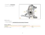
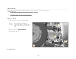
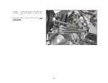
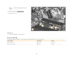
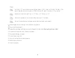
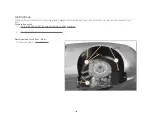
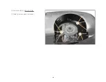
Page 131: ... 007 Secure lift vehicle on lifting platform 2 AA RM 03B03 01 001 Remove install wheels 3 AA RM 02A02 03 001 Remove install wheel arch liner rear Remove tie rod Rear Care Point Use ball joint splitter to separate 1 Remove nut 1 M12 70 Nm 2 Pull back dust cover 2 3 Unscrew tie rod 3 from aluminium subframe 4 M16 x 1 5 80 Nm 4 Remove tie rod 3 130 ...

Page 132: ...16 x 1 5 80 Nm 1 Install components in reverse order 2 Perform geometry check 3 Check chassis geometry AA RM 03B03 01 002 Perform a wheel alignment check Torque settings FG03 Chassis B02 Rear Suspension Rear Suspension LH AA RM 03B02 01 007 Remove install tie rod Rear Description Dimension Value Nut Tie rod Upright M12 70 Nm Bolt Tie rod Aluminium subframe M16 x 1 5 80 Nm Bolt Tie rod Aluminium su...

Page 133: ...Description Dimension Value Nut Tie rod Upright M12 70 Nm Bolt Tie rod Aluminium subframe M16 x 1 5 80 Nm Bolt Tie rod Aluminium subframe M16 x 1 5 80 Nm 132 ...

Page 134: ...M 03B03 01 001 Remove install wheels 3 AA RM 03C02 01 002 Remove install caliper parking brake 4 AA RM 03C01 03 001 Remove install brake caliper rear 5 AA RM 02A02 03 007 Remove install cooling duct 6 AA RM 03C01 03 002 Remove install brake disc rear Remove upright Rear 1 Remove electronic park brake EPB caliper bracket bolts 2 Remove EPB caliper bracket 3 Remove driveshaft nut 1 M26 320 Nm 133 ...

Page 135: ...haft nut 1 M26 320 Nm 4 Remove nut 2 M12 70 Nm Care Point Use ball joint separator 5 Detach track rod from upright 6 Remove bolt 3 M14 x 110 90 Nm 7 Remove nut 4 Care Point Observe excentric stepped washer Care Point Use ball joint separator 8 Detach upper wishbone 5 from upright 6 9 Remove bolt 3 134 ...

Page 136: ... Detach track rod from upright 6 Remove bolt 3 M14 x 110 90 Nm 7 Remove nut 4 Care Point Observe excentric stepped washer Care Point Use ball joint separator 8 Detach upper wishbone 5 from upright 6 9 Remove bolt 3 10 Remove upright Rear 6 Remove upright Rear 135 ...

Page 137: ...nment check Care Point Once vehicle is on ground 3 Apply pressure to top of wheel towards vehicle If excessive inward movement of wheel is present the upper ball joint has failed The wishbone will require replacing Torque settings FG03 Chassis B02 Rear Suspension Rear Suspension LH AA RM 03B02 01 003 Remove install upright Rear Description Dimension Value Nut Driveshaft M26 320 Nm Nut Tie rod Upri...

Page 138: ...5M02 01 007 Remove install sensor rear wheel speed 7 AA RM 03C01 03 002 Remove install brake disc rear 8 AA RM 03B02 01 003 Remove install upright CAUTION Risk of injury when unscrewing micro encapsulated bolts There is an increased risk of injury when unscrewing micro encapsulated bolts due to the sudden breakaway torque Always replace bolts with locking splines microencapsulated bolts and self l...

Page 139: ... Install in reverse order 2 Check chassis geometry AA RM 03B03 01 002 Perform a wheel alignment check Torque settings FG03 Chassis B02 Rear Suspension Rear Suspension LH AA RM 03B02 01 004 Remove install hub Rear Description Dimension Value Bolt Wheel hub Upright M12 x 30 70 Nm 138 ...

Page 140: ...04 04 007 Secure Lift vehicle on lifting platform 2 AA RM 03B03 01 001 Remove Install wheels Remove drop link 1 Detach wheel arch liner in mounting area Care Point Mark upper side of drop link Convex washers on left hand side only Plain washer on right hand side 2 Remove bolts 1 M14 x 60 100 Nm 3 Remove drop link 2 Install drop link 139 ...

Page 141: ...o not apply tension to Z bar 1 Install in reverse order Torque settings FG03 Chassis B02 Rear Suspension Rear Suspension LH AA RM 03B02 01 006 Remove install drop link Description Dimension Value Bolt Drop link M14 x 60 100 Nm 140 ...

Page 142: ...stall wheels 3 AA RM 02A04 04 001 Remove install floor panel engine fuel tank 4 AA RM 02A04 04 004 Remove install rear diffusor Remove Z bar 1 Detach wheel arch liner in mounting area on both sides Care Point Convex washers on left hand side only Plain washer on right hand side 2 Remove bolts 1 on both sides of Z bar M14 x 60 100 Nm Care Point Observe the position of shims 3 Remove bolts 2 M8 x 20...

Page 143: ... on both sides Care Point Convex washers on left hand side only Plain washer on right hand side 2 Remove bolts 1 on both sides of Z bar M14 x 60 100 Nm Care Point Observe the position of shims 3 Remove bolts 2 M8 x 20 23 Nm 4 Remove Z bar 3 142 ...

Page 144: ...Nm 4 Remove Z bar 3 Install Z bar 1 Install components in reverse order Torque settings FG03 Chassis B02 Rear Suspension Z Bar Assembly AA RM 03B02 04 001 Remove install Z bar Description Dimension Value Bolt Drop link M14 x 60 100 Nm Bolts Z bar Floor M8 x 20 23 Nm 143 ...

Page 145: ...the flat floor on the front and rear axle lines Care Point Specified ride heights 120mm front 140mm rear with driver and half tank of fuel Tolerance 2mm 3 Ensure vehicle is at correct ride height Care Point Tyre pressure Front 19in Wheels 2 0 Bar Rear 20in Wheels 2 2 Bar 4 Ensure the vehicle wheels are pointed in the straight ahead position 5 Ensure the tyres are a matched axle set and at the corr...

Page 146: ...ar 1 0 Tolerance 0 1 Care Point Caster is not adjustable but its nominal setting is between 4 5 positive Care Point Carry out camber adjustment using the camber adjustment tophat on the upright 8 Check for signs of wear or damage to the suspension components 9 Carry out vehicle alignment 10 Connect McLaren Diagnostic System proceed to Diagnostic Toolbox within Steering Angle Sensor SAS 11 Access Q...

Page 147: ...A RM 02A02 03 001 Remove install wheel arch liner Rear Preparation work 1 AA RM 02A04 04 007 Secure lift vehicle on lifting platform 2 AA RM 03B03 01 001 Remove Install wheel Remove wheel arch liner Rear 1 Remove bolts 1 M6 x 16 5 Nm 2 Remove bolts 2 M6 x 16 5 Nm 3 Partially remove wheel arch liner 146 ...

Page 148: ...2 Remove bolts 2 M6 x 16 5 Nm 3 Partially remove wheel arch liner 4 Disconnect tyre pressure monitor trigger electrical connector 4 5 Remove wheel arch liner 5 147 ...

Page 149: ...monitor trigger electrical connector is located correctly 1 Install components in reverse order Torque settings FG02 Body Systems A02 Exterior Trim Lighting Wipers Luggage Cell Ducts Wheelarch Liners AA RM 02A02 03 001 Remove install wheel arch liner Rear Description Dimension Value Bolt Wheel arch liner M6 x 16 5 Nm Bolt Wheel arch liner M6 x 16 5 Nm 148 ...

Page 150: ...fting platform 2 AA RM 02A04 04 001 Remove install floor panel engine fuel tank Drain fluid Engine oil 1 Remove cover 1 Care Point Ensure header tank clamps do not drop into the engine bay 2 Remove bolts with washers 2 M6 x 16 6 Nm Care Point Use 10mm flexi head ratchet spanner Care Point Spacer is fitted between bracket and nut Ensure this does not fall into the engine bay 149 ...

Page 151: ...ot fall into the engine bay Care Point Ensure grommet remains in place on header tank bracket 3 Remove nut 3 M6 6 Nm Care Point Ensure that the hoses connected to the coolant reservoir do not become detached put under high tension or become damaged during detachment and moving of the coolant reservoir to gain access to oil filter cap Protect the area sufficiently before carrying out this step 4 Re...

Page 152: ...Remove oil filter cap 4 25 Nm Care Point Use a suitable container to catch the excess fluid Care Point Drain oil whilst at a warm temperature Allow oil to drain for at least 15 minutes Care Point Oil must also be drained from the turbocharger oil return hoses AA RM 04F01 01 035 Remove install turbo charger oil return hose Only disconnect the oil return hoses from the engine ladderframe Renew O rin...

Page 153: ...l must also be drained from the turbocharger oil return hoses AA RM 04F01 01 035 Remove install turbo charger oil return hose Only disconnect the oil return hoses from the engine ladderframe Renew O ring on the oil return hose if it has become damaged 5 Remove plug 5 T50 24 Nm 6 Remove bolt 6 M14 18 Nm 7 Drain engine oil 8 Remove oil filter 9 Fill fluid Engine oil 152 ...

Page 154: ...y of oil to the tank at any one time Do not choke the filler tube with oil under any circumstances Care Point Do not put more than 6 8 litres of oil into the system If this quantity has been achieved with no movement to the oil level gauge please give the vehicle a complete check of the oil system including use of the McLaren Diagnostic System Under no circumstances should the above mentioned quan...

Page 155: ...nces should the above mentioned quantity be exceeded 7 Fill up engine oil slowly using a funnel Mobil 1 0W40 8 Check oil level AA RM 04F02 01 007 Check oil level Care Point Ensure oil filler cap is fitted correctly The cap should align parallel with the vehicle Front to back 9 Install oil filler cap 8 10 Install components in reverse order Torque settings FG04 Powertrain F02 Oil System Engine Oil ...

Page 156: ...lue Bolt Reservoir coolant Bracket M6 x 16 6 Nm Nut Reservoir coolant Bracket M6 6 Nm Oil filter cap Engine 25 Nm Plug engine oil drain engine T50 24 Nm Bolt engine oil drain oil tank M14 18 Nm Oil filter cap Engine 25 Nm 155 ...

Page 157: ...s can cause severe burns to the skin and eyes If glowing objects come into contact with water hot steam or hot splashing water this can result in severe skin and eye burns Severe and possibly permanent injuries can result if hot or glowing objects come into contact with unprotected skin or eyes Fire can result if glowing objects come into contact with flammable materials or substances Wear protect...

Page 158: ... sealing face of old gasket area Replace oil with the exact quantity that was removed Replace paper gasket Replace o ring seal if damaged P80 THIX If new hose is being fitted this will already be fitted with an o ring and paper gasket 1 Install components in reverse order 2 Check engine for leaks 3 Check oil level AA RM 04F02 01 007 Check oil level Description Dimension Value 157 ...

Page 159: ...Bolt Oil drain pipe Turbo charger engine M6 x 16 10 Nm Bolt Oil drain pipe Turbo charger engine M6 x 16 10 Nm 158 ...

Page 160: ...l air filter Preparation work 1 AA RM 02A04 04 007 Secure lift vehicle on lifting platform 2 AA RM 03B03 01 001 Remove Install wheels 3 AA RM 02A02 03 001 Remove Install wheel arch liner Rear Remove air filter 1 Remove bolts 1 M5 x 16 3 Nm 2 Remove airbox access hatch 2 3 Remove air filter 3 159 ...

Page 161: ...lter and airbox are clean and free of debris 1 Install components in reverse order Torque settings FG04 Powertrain F01 Power Unit Air Intake System AA RM 04F01 02 002 Remove install air filter Description Dimension Value Bolt Airbox service panel M5 x 16 3 Nm 160 ...

Page 162: ...stem is pressurized If the cooling system is opened suddenly there is a risk of scalding from hot coolant which splashes out If coolant is swallowed symptoms of poisoning such as headaches dizziness stomach pain respiratory paralysis unconsciousness vomiting and cramps can occur Wear protective gloves protective clothing and eye protection Allow cooling system to cool down to a coolant temperature...

Page 163: ...1 Remove coolant reservoir cap 1 Care Point Use a suitable container to catch the coolant 2 Detach clamps 2 4 3 Detach coolant hoses 3 5 from water pump and front cover 162 ...

Page 164: ...amps 2 4 3 Detach coolant hoses 3 5 from water pump and front cover Care Point Use a suitable container to catch the coolant 4 Remove clamp 6 right hand side and left hand side 5 Detach coolant hoses 7 right hand side and left hand side from low temperature radiator 163 ...

Page 165: ... Use a suitable container to catch the coolant 4 Remove clamp 6 right hand side and left hand side 5 Detach coolant hoses 7 right hand side and left hand side from low temperature radiator Fill fluid coolant 164 ...

Page 166: ...lant mix ratio of 50 50 with water Care Point Use MOBIL 1 Anti Freeze EXTRA Care Point Ensure vacuum box is in a higher position than the coolant reservoir throughout the filling procedure Care Point Ensure all relevant Personal Protective Equipment PPE is worn when carrying out this procedure gloves goggles etc 2 Attach adaptor to coolant reservoir 8 3 Connect vacuum pump to coolant fill adaptor ...

Page 167: ...mp to coolant fill adaptor 8 4 Connect vacuum box to coolant fill adaptor 9 5 Close all valves on vacuum box Venturi 10 Top 11 Lower 12 Fill 13 6 Attach air line to top box connection 14 7 Open top and lower valves on the vacuum box 11 12 Care Point Do not exceed a vacuum of 0 5 bar vacuum at this stage 8 Gradually open Venturi valve 10 on vacuum box to generate vacuum in system Care Point Vacuum ...

Page 168: ... If the vacuum cannot be held please check system for leaks 9 Close top valve 11 and ensure system can hold a vacuum 10 Release vacuum by closing Venturi valve 10 and opening top valve 11 11 Close lower valve 12 Care Point Place open end of filler tube in to separate coolant filled container Please ensure a minimum of 10 litres of coolant 50 50 mix with water is in the separate container 12 Connec...

Page 169: ...necting the vacuum box to the coolant reservoir or the box becomes full 19 Close Venturi valve 10 and allow coolant to be drawn into the vehicle 20 Repeat steps 10 18 21 Detach equipment from vehicle 22 Drain all coolant from vacuum box 23 Repeat steps 2 10 Care Point Ensure vacuum box fill level does not exceed sight level Care Point During this stage of the procedure do not exceed 0 8 bar vacuum...

Page 170: ... 26 Once vehicle has been filled carry out a short vehicle run up and repeat steps 2 24 Care Point Ensure coolant reservoir is filled to the minimum level Once the reservoir is at the correct level add an additional 350ml of coolant mix 27 Install components in reverse order 169 ...

Page 171: ...move install wheel arch liner Rear 4 AA RM 02A04 04 008 Remove install transmission floor panel Drain fluid Clutch Care Point Ensure the clutches are opened no gears engaged no torque and operate airbrake a minimum of 2 times 1 Run engine for 2 minute at 2000 rpm Care Point Ensure airbrake is in a retracted position 2 Stop engine Care Point Ensure area around fill plug is cleaned with solvent befo...

Page 172: ...ure area around fill plug is cleaned with solvent before removing fill plug 3 3 Remove fill plug 3 Care Point Use a suitable container to catch the excess fluid 4 Remove both drain plugs 1 2 Care Point Allow approximately 5 minutes for oil to drain 5 Let the oil drain completely 171 ...

Page 173: ...process must be followed quickly so the clutch fluid will not drain back into clutch sump Care Point Ensure a very clean funnel and pipe are used Fill using new clutch oil only 2 Fill clutch fluid to fill plug 3 level Pentosin FFL 4 3 Install drain plug 1 torque to 10 Nm to avoid stress damage on threads 4 Install fill plug 3 torque to 10 Nm to avoid stress damage on threads Care Point Ensure the ...

Page 174: ... 7 Remove fill plug 3 Care Point Use a suitable container to catch the excess fluid 8 Remove drain plug 1 Care Point Approximately 1 0 litre of clutch fluid will be lost Flow of clutch oil will not stop completely 9 Allow clutch oil to drain for 60 seconds Care Point Drain plug 1 should remain removed 10 Immediately top up the clutch fluid within one minute until clutch fluid starts to drain out o...

Page 175: ... 0 litres Pentosin FFL 4 Care Point Renew washer on fill plug 3 16 Install the fill plug 3 torque fully 50 Nm 17 Install components in reverse order Torque settings FG04 Powertrain G01 Transmission Transmission AA RM 04G01 01 015 Drain fill fluid Clutch Description Dimension Value Clutch fill and drain plug 50 Nm Plug Clutch oil drain fill Fill torque 10 Nm Plug Clutch oil drain fill Fill torque 1...

Page 176: ...ter Clutch fluid Preparation work 1 AA RM 02A04 04 007 Secure lift vehicle on lifting platform 2 AA RM 02A04 04 008 Remove install transmission floor panel 3 AA RM 04G01 01 015 Clutch oil drain and refill Remove filter Clutch fluid 1 Remove bolts 1 M6 x 16 10 Nm 2 Remove filter Clutch fluid 3 175 ...

Page 177: ...e from dirt and debris to avoid contamination 1 Install components in reverse order 2 Check transmission for leaks Torque settings FG04 Powertrain G01 Transmission Transmission AA RM 04G01 01 017 Remove install filter Clutch fluid Description Dimension Value Bolt Fluid cooler clutch Transmission M6 x 16 10 Nm 176 ...

Page 178: ...04 04 004 Remove install floor panel rear diffuser Preparation work 1 AA RM 02A04 04 007 Secure lift vehicle on lifting platform Remove floor panel rear diffuser Care Point Two technicians required 1 Remove caps 1 2 Remove bolts 2 M6 x 16 6 Nm 3 Remove torx bolts 3 M6 x 16 6 Nm 177 ...

Page 179: ...2 Remove bolts 2 M6 x 16 6 Nm 3 Remove torx bolts 3 M6 x 16 6 Nm 5 Disconnect fog reverse lamp electrical connector 5 6 Remove diffuser 6 178 ...

Page 180: ...components in reverse order 2 Check functionality of light and camera Torque settings FG02 Body Systems A04 Panels Glazing Paint Floors Diffuser AA RM 02A04 04 004 Remove install floor panel rear diffuser Description Dimension Value Bolt Diffuser Wheel Arch Liner M6 x 16 6 Nm Bolt Torx Diffuser Frame M6 x 16 6 Nm 179 ...

Page 181: ... 04 007 Secure lift vehicle on lifting platform 2 AA RM 02A04 04 004 Remove install floor panel rear diffuser Care Point Use a suitable container to catch the excess fluid Drain fluid Transmission oil 1 Remove drain plug 1 Care Point Allow approximately 2 minutes for oil to drain 2 Let the oil drain completely Fill fluid Transmission oil 180 ...

Page 182: ...plug 2 approximately 3 litres Mobil PTX 75W 90 4 Install the plug 2 Care Point Ensure the clutches are opened no gears engaged no torque 5 Run the engine for 2 minute at idle speed 6 Remove the plug 2 Care Point Level needs to be topped up within a minute of the stopping engine and removing plug 2 7 Top up transmission oil until it reaches the 181 ...

Page 183: ...engine until transmission oil temperture reaches a minimum of 95 C 10 Remove the plug 2 Care Point Level needs to be topped up within a minute of reaching 95 C and removing the plug 2 11 Top up transmission oil until it reaches the level plug 2 12 Renew fill plug copper washer 13 Install the plug 2 50 Nm Torque settings FG04 Powertrain G01 Transmission Transmission AA RM 04G01 01 014 Drain fill fl...

Page 184: ...ration work 1 AA RM 02A04 04 007 Secure lift vehicle on lifting platform 2 AA RM 02A04 04 008 Remove install transmission floor panel 3 AA RM 04G01 01 014 Transmission oil drain and refill Remove filter Transmission fluid 1 Remove bolt 1 M6 x 16 10 Nm 2 Remove filter Transmission fluid 2 Install filter Transmission fluid 183 ...

Page 185: ...contamination 1 Install components in reverse order 2 Check transmission for leaks Torque settings FG04 Powertrain G01 Transmission Transmission AA RM 04G01 01 016 Remove install filter Transmission fluid Description Dimension Value Bolt Filter transmission fluid Transmission M6 x 16 10 Nm 184 ...

Page 186: ...M 03L01 01 005 Drain fill cooling system 9 AA RM 02A05 01 009 Draining and filling air conditioning 10 AA RM 02A04 03 007 Remove install bodyside lower 11 Care Point Up to MY14 AA RM 02A04 03 010 Remove install panel Side lower 12 Care Point From MY15 AA RM 02A04 03 010 Remove install panel Side lower MY15 13 Care Point Up to MY14 AA RM 02A02 02 005 Remove install radiator grille 14 Care Point Fro...

Page 187: ... Fuels are highly inflammable and toxic if inhaled Fuel vapours are explosive invisible and spread out at floor level This vapour is poisonous when inhaled and has an anesthetizing effect in high concentrations Fuel can cause damage to skin For example skin is degreased when it comes into contact with gasoline fuel Observe the national safety precautions and regulations Keep fuel away from fire op...

Page 188: ...2 3 Disconnect electrical connectors 3 4 Remove harness carrier with harness 5 Remove fuel feed line tank to engine bay 4 6 Detach purge line 5 Care Point Filter is on left hand access cover 7 Remove bolts 6 M6 x 16 8 Nm 8 Remove retaining ring 7 187 ...

Page 189: ... engine bay 4 6 Detach purge line 5 Care Point Filter is on left hand access cover 7 Remove bolts 6 M6 x 16 8 Nm 8 Remove retaining ring 7 9 Remove access cover with fuel filter 8 partially 10 Disconnect electrical connectors 9 11 Detach fuel line 10 12 Remove access cover with fuel filter 8 completely 188 ...

Page 190: ...ompletely Install fuel filter 1 Renew access cover with fuel filter 2 Renew sealing ring 3 Install components in reverse order Torque settings FG03 Chassis K01 Fuel System Fuel Tank AA RM 03K01 01 001 Remove install fuel filter Description Dimension Value Nut harness carrier Fuel tank M6 8 Nm Bolts with washers Access cover retaining ring M6 x 16 8 Nm 189 ...

Page 191: ...ve install cover door shut Rear lower Care Point Risk of paint damage Remove cover door shut Rear lower 1 Open door 2 Use tape to prevent paint damage 3 Remove arrows cover door shut 1 using suitable trim tool Install cover door shut Rear lower 1 Install components in reverse order 190 ...

Page 192: ... Secure lift vehicle on lifting platform 2 AA RM 03B03 01 001 Remove install wheels 3 AA RM 02A02 03 001 Remove install wheel arch liner Rear 4 AA RM 02A03 03 003 Remove install cover door shut rear lower Care Point Risk of paint damage Remove bodyside lower Rear 1 Open door 2 Use tape to prevent paint damage arrows 3 Prise out cover door shut 1 4 Remove bolts 2 M6 x 20 8 Nm 191 ...

Page 193: ...1 Open door 2 Use tape to prevent paint damage arrows 3 Prise out cover door shut 1 4 Remove bolts 2 M6 x 20 8 Nm 192 ...

Page 194: ...4 Remove bolts 2 M6 x 20 8 Nm 5 Remove bolts 3 M6 x 16 8 Nm 193 ...

Page 195: ...5 Remove bolts 3 M6 x 16 8 Nm 6 Remove bolts 4 M6 x 16 8 Nm 194 ...

Page 196: ...6 Remove bolts 4 M6 x 16 8 Nm 7 Remove bodyside lower rear arrows 195 ...

Page 197: ...7 Remove bodyside lower rear arrows Install bodyside lower Rear 1 Install components in reverse order 196 ...

Page 198: ... lower Up to MY14 Preparation work 1 AA RM 02A03 03 003 Remove install cover door shut rear lower 2 AA RM 02A04 03 007 Remove Install panel bodyside rear lower Remove panel Side lower Up to MY14 Care Point Risk of paint damage 1 Detach arrow cover 1 2 Remove bolts 2 M10x20 5 Nm 3 Remove nuts 3 M6 6 Nm 4 Remove side lower panel 4 197 ...

Page 199: ... Up to MY14 1 Install components in reverse order Torque settings FG02 Body Systems A04 Panels Glazing Paint Roof Panels Fenders Fuel Filler AA RM 02A04 03 010 Remove install panel Side lower Up to MY14 Description Dimension Value Bolt Panel Side lower top M10x20 5 Nm Nut Panel Side lower lower M6 6 Nm 198 ...

Page 200: ...1 AA RM 02A04 04 007 Secure lift vehicle on lifting platform 2 AA RM 03B03 01 001 Remove Install wheels 3 AA RM 02A02 03 001 Remove Install wheel arch liner Rear 4 AA RM 02A03 03 003 Remove install cover door shut rear lower 5 AA RM 02A04 03 007 Remove Install panel bodyside rear lower 6 AA RM 02A04 03 010 Remove install panel side lower Remove radiator grille Up to MY14 199 ...

Page 201: ...grille Up to MY14 1 Install components in reverse order Torque settings FG02 Body Systems A02 Exterior Trim Lighting Wipers Finishers Badges Grilles Decals AA RM 02A02 02 005 Remove install radiator grille Up to MY14 Description Dimension Value Screw Grille to Bodyside M6 x 16 5 Nm Button Head Screw Grille to Rocker Panel M6 x 16 5 Nm Screw Grille Radiator Duct 2 Nm 200 ...

Page 202: ...d generator 1 Remove inlet manifold cover 2 Detach hose 1 3 Remove clamp 2 M6 5 Nm 4 Remove engine intake sound generator Install engine intake sound generator 1 Install components in reverse order 2 Check functionality Torque settings FG04 Powertrain F01 Power Unit Power Unit AA RM 04F01 01 037 Remove Install engine intake sound generator 201 ...

Page 203: ...Description Dimension Value Clamp ISG to Throttle M6 5 Nm 202 ...

Page 204: ...e Cover AA RM 02A03 04 005 Remove install engine compartment side cover Remove cover Care Point Apply tape in the following areas A on point of bodyside rears rear deck and engine side covers in gas strut hinge area 1 Apply tape A 2 Remove cover 1 203 ...

Page 205: ... flexi head ratchet spanner Care Point Clamp is fitted between bracket and nut Ensure this does not fall into the engine bay Care Point Ensure grommet remains in place on header tank bracket 4 Remove nut 3 M6 6 Nm Care Point Ensure that the hoses connected to the coolant reservoir do not become detached put under high tension or become damaged 204 ...

Page 206: ...Point Ensure that the hoses connected to the coolant reservoir do not become detached put under high tension or become damaged during detachment and rotation Protect the area sufficiently before carrying out this step 5 Move coolant reservoir 4 into raised position and turn 90 Care Point Use second operater to hold engine cover Care Point Remove gas strut and lower ball stud 10 Nm for side you wan...

Page 207: ... side cover 7 9 Refit lower ball stud 10 Nm and gas strut 10 Repeat steps 6 8 for opposite side Install engine compartment side cover Care Point Risk of component damage 1 Install components in reverse order Torque settings FG02 Body Systems A03 Closures Engine Cover AA RM 02A03 04 005 Remove install engine compartment side cover Description Dimension Value Bolt Reservoir coolant Bracket M6 x 16 6...

Page 208: ...voir coolant Bracket M6 x 16 6 Nm Nut Reservoir coolant Bracket M6 6 Nm Ball stud Engine Cover 10 Nm Bolt Engine compartment side cover Body M6 x 16 4 Nm Bolt Engine compartment side cover Body M6 x 12 5 Nm Ball stud Engine Cover 10 Nm 207 ...

Page 209: ...ng on running or rotating engine with cranking speed Detach the crankshaft position sensor connection either at the control unit or at the position sensor Do not install any electrically conducting uninsulated adapters or installation sensors into the ignition cable WARNING Risk of burning and fire when handling hot or glowing objects Unprotected contact with hot or glowing objects can cause sever...

Page 210: ...1 Detach crankcase ventilation hoses 1 A B from the oil tank 2 Move crankcase breather 2 in direction C 3 Note overview of cylinder sequence 1 8 209 ...

Page 211: ... 4 and 8 once bolt 4 is removed turn 180 to disconnect electrical connectors 3 Care Point Remove ignition coils 7 4 and 8 first to allow better access to disconnect ignition coils 7 3 and 7 4 Disconnect electrical connectors 3 Care Point To remove bolt under frame for ignition coils 7 3 and 7 access bolts from opposite side of vehicle with a magnetic socket 210 ...

Page 212: ... for ignition coils 7 3 and 7 access bolts from opposite side of vehicle with a magnetic socket 5 Remove bolt 4 M6 x 20 6 Nm Care Point Prevent debris from falling in whilst selecting tools for spark plug removal 6 Remove ignition coil 5 Care Point For spark plugs in position 1 and 5 the following tools are required bent handle flexi head 3 8 drive ratchet with 6 locking extension 14mm spark plug ...

Page 213: ... plug socket that is either magnetic or has an interference fit For all the remaining 6 spark plugs the following tools are required bent handle flexi head ratchet with 2 locking extension universal joint 14mm spark plug socket that is either magnetic or has an interference fit Care Point Prevent debris from falling in whilst selecting tools for spark plug 7 removal 7 Remove spark plugs 7 NGK T202...

Page 214: ...ires before installing engine side covers Care Point Please follow the sequence when installing the ignition coil 1 Ensure correct fittment of plug 2 Rotate coil 90 degrees clockwise while applying firm downward pressure 3 Rotate 180 degrees anti clockwise while applying firm downward pressure 4 Rotate 90 degrees anti clockwise to sit above engine mount 3 Install components in reverse order 4 Read...

Page 215: ...otate coil 90 degrees clockwise while applying firm downward pressure 3 Rotate 180 degrees anti clockwise while applying firm downward pressure 4 Rotate 90 degrees anti clockwise to sit above engine mount 3 Install components in reverse order 4 Read out delete error memory Torque settings FG04 Powertrain F01 Power Unit Power Unit AA RM 04F01 01 026 Remove install spark plug Description Dimension V...

Page 216: ...is mileage chart against vehicle odometer reading whilst carrying out service Customer km miles Vehicle registration VIN Date Colour Service Time Task specific Address Replace clutch oil and filter Every 30 000km only or 20 000 miles only Replace transmission oil and clean filter Every 60 000 km or 40 000 miles only Document Number AA RM 02A03 04 006 Document Title Remove install side cover Engine...

Page 217: ...Portal for any outstanding campaigns on vehicle 1 1 Check for wheel locking key if supplied 2 7 Check gaps and seals of doors engine cover and luggage compartment lid 2 8 Check fuel filler flap manual opening 2 1 Check exterior lighting function 2 2 Check headlamp windscreen washer system 2 3 Check headlamp adjustment Ref AA RM 02A02 04 003 2 4 Replace wiper blade 2 5 Check window glazing 2 6 Chec...

Page 218: ...uid level of power steering Ref AA RM 03D01 01 008 2 14 Check adjust fluid level of windshield washer system Interior function checks 3 0 Carry out cluster checks 3 1 Check battery condition 5 7 Check condition and operation of seat belts buckles ensure belts are not twisted 5 8 Check brake pedal free play 5 9 Check operation of EPB Electronic Parking Brake Mechanical checks 6 0 Secure lift vehicl...

Page 219: ... required 9 2 Check Z bar drop links for play 9 3 Check clean air filter elements replace as required Ref AA RM 04F01 02 002 9 4 Check transmission and clutch fluids are not overfilled 9 5 Check front lower exhaust manifold nuts studs and exhaust manifold 9 6 Check radiator low temp cooler condition check for any damage clean as necessary 10 0 Lower vehicle 8 4 Check engine mounts 8 5 Tighten scre...

Page 220: ...and fobs 15 3 Check for towing eye 14 0 Road test carry out 14 1 and 14 2 whilst on test Max 30 min 6 miles 13 2 Replace engine ISG Intake Sound Generator Ref AA RM 04F01 01 037 13 3 Check corrosion antifreeze protection and enter here C 13 4 Check exhaust emission label market specific 13 5 Check injection ignition system connections and harness 13 6 Check adjust fluid level of cooling system 14 ...

Page 221: ...ove install floor panel Engine fuel tank AA RM 04F02 01 011 Drain and refill engine oil AA RM 03B01 02 003 Remove install upper wishbone front AA RM 03B02 01 001 Remove install upper wishbone rear AA RM 02A04 04 008 Remove install transmission floor panel AA RM 03B01 02 002 Remove install lower wishbone front AA RM 02A04 04 002 Remove install floor panel Front AA RM 03B02 01 002 Remove install low...

Page 222: ... Service sheet 2nd year or 30 000 km 20 000 miles Please check vehicle odometer reading against mileage dependant task service sheet before carrying out service Customer km miles Vehicle registration VIN Date Service Time 6 8 units 1 3 Inspect wheel rim condition 1 4 Check bodywork 1 5 Check McLaren Retailer Portal for any outstanding campaigns on vehicle Check paint and panels for defects please ...

Page 223: ... out interior functional checks 2 9 Check controls and adjusters in general hinges doors luggage lid and engine cover Interior function checks 3 0 Carry out cluster checks 3 1 Check battery condition 5 7 Check condition and operation of seat belts buckles ensure belts are not twisted 5 8 Check brake pedal free play 5 9 Check operation of EPB Electronic Parking Brake Mechanical checks 6 0 Secure li...

Page 224: ...01 9 1 Drain engine oil Ref AA RM 04F02 01 011 9 2 Check Z bar drop links for play 9 3 Replace air filter Ref AA RM 04F01 02 002 9 6 Replace clutch oil and filter only if mileage achieved Ref AA RM 04G01 01 015 021 9 4 Check radiator low temp cooler condition check for any damage clean as necessary 8 4 Check engine mounts 8 5 Tighten screws nuts and bolts including exhaust system clips and strips ...

Page 225: ...in 6 miles 14 1 Check airbrake function 14 2 Check navigation system if fitted 15 0 Finish road test and carry out documents safety device final checks 13 1 Check wheel bolt torque values 130 Nm 13 2 Replace engine ISG Intake Sound Generator Ref AA RM 04F01 01 037 13 3 Check corrosion antifreeze protection and enter here C 13 4 Check exhaust emission label market specific 13 5 Check injection igni...

Page 226: ...brake AA RM 02A04 04 003 Remove install floor panel Tunnel AA RM 02A04 04 005 Remove install floor panel Rear lower extension AA RM 02A04 04 006 Remove install guide vane Printed copy is not controlled AA RM 04G01 01 015 Remove install fluid Transmission Clutch Consumables Sundries Comments AA RM 04G01 01 017 Remove install filter Transmission Clutch fluid AA RM 04F02 01 003 Remove install Oil Fil...

Page 227: ...f doors engine cover and luggage compartment lid 2 8 Check fuel filler flap manual opening MP4 12C Coupe Service sheet 3rd year or 45 000 km 30 000 miles Please check vehicle odometer reading against mileage dependant task service sheet before carrying out service Customer km miles Vehicle registration VIN Date 2 1 Check exterior lighting function 1 3 Inspect wheel rim condition 1 4 Check bodywork...

Page 228: ...interior controls switches lights windows and parking sensors if fitted 5 3 Check heated rear window function 5 4 Check operation of heating ventilation and air conditioning system 5 5 Check condition of interior trim seats door casings centre console facia carpets 5 6 Check exterior door mirrors function and powerfold rear view mirror and sun visors 3 2 Check engine oil level Ref AA RM 04F02 01 0...

Page 229: ...e bleed as required Ref AA RM 03C01 01 005 7 5 Check clean air ducts of brake system 8 0 Remove all under floors Ref AA RM 02A04 04 001 002 003 005 006 008 8 1 Check all visible parts for routing leaks and damage cooling system 9 5 Check radiator low temp cooler condition check for any damage clean as necessary 10 0 Lower vehicle 10 1 Replace engine oil filter Ref AA RM 04F02 01 003 10 2 Fill engi...

Page 230: ...sion antifreeze protection and enter here C 13 4 Check exhaust emission label market specific Underside of vehicle 12 0 Install all under floors Ref AA RM 02A04 04 001 002 003 005 006 008 12 1 Check tyre orientation damage and crack formations 12 2 Install wheels Ref AA RM 03B03 01 001 15 0 Finish road test and carry out documents safety device final checks 15 2 Check function of all keys locks an...

Page 231: ...anel Front AA RM 02A04 04 003 Remove install floor panel Tunnel AA RM 03B02 01 001 Remove install upper wishbone rear AA RM 02A04 04 008 Remove install transmission floor panel AA RM 03B01 02 002 Remove install lower wishbone front AA RM 04F02 01 003 Remove install Oil Filter AA RM 03B02 01 002 Remove install lower wishbone rear AA RM 04F02 01 011 Drain and refill engine oil Printed copy is not co...

Page 232: ... and panels for defects please mark the picture as following D dent S scratch X damage Vehicle exterior fluid and battery checks ensure battery charger and body protection are fitted 2 0 Two technicians will be required for steps 2 1 and 2 2 Service Time 6 8 units Address 1 0 Vehicle pre checks 1 1 Check for wheel locking key if supplied 1 2 Check tyre orientation damage and crack formations 2 7 C...

Page 233: ...AA RM 03C01 01 005 2 13 Check adjust fluid level of power steering Ref AA RM 03D01 01 008 2 14 Check adjust fluid level of windshield washer system Interior function checks 3 0 Carry out cluster checks 3 1 Check battery condition 5 7 Check condition and operation of seat belts buckles ensure belts are not twisted 5 8 Check brake pedal free play 5 9 Check operation of EPB Electronic Parking Brake M...

Page 234: ... 04F01 02 002 8 2 Check powertrain system for leaks engine transmission and exhaust 8 3 Check all visible steering components for leaks and damage 8 4 Check engine mounts 8 5 Tighten screws nuts and bolts including exhaust system clips and strips in general 8 6 Check torques on suspension Ref AA RM 03B01 02 002 003 03B02 01 001 002 8 7 Check condition of drive shafts 10 4 Top up and re check level...

Page 235: ...t Max 30 min 6 miles 12 2 Replace wheel nut bolts 12 3 Install wheels Ref AA RM 03B03 01 001 13 0 Lower vehicle to ground 13 1 Check wheel bolt torque values 130 Nm 13 2 Replace engine ISG Intake Sound Generator Ref AA RM 04F01 01 037 13 3 Check corrosion antifreeze protection and enter here C 15 5 Report and rectify all recorded defects 15 6 Check stamp service and warranty guide 14 1 Check airbr...

Page 236: ...stall floor panel Rear lower extension AA RM 02A04 04 006 Remove install guide vane AA RM 02A04 04 002 Remove install floor panel Front AA RM 02A04 04 003 Remove install floor panel Tunnel AA RM 03B02 01 001 Remove install upper wishbone rear AA RM 02A04 04 008 Remove install transmission floor panel AA RM 03B01 02 002 Remove install lower wishbone front AA RM 03B02 01 002 Remove install lower wis...

Page 237: ...nels for defects please mark the picture as following D dent S scratch X damage Vehicle exterior fluid and battery checks ensure battery charger and body protection are fitted 2 0 Two technicians will be required for steps 2 1 and 2 2 Colour Service Time 5 85 units Address 1 0 Vehicle pre checks 1 1 Check for wheel locking key if supplied 1 2 Check tyre orientation damage and crack formations 2 7 ...

Page 238: ...ke system 2 13 Check adjust fluid level of power steering Ref AA RM 03D01 01 008 2 14 Check adjust fluid level of windshield washer system Interior function checks 3 0 Carry out cluster checks 3 1 Check battery condition 5 7 Check condition and operation of seat belts buckles ensure belts are not twisted 5 8 Check brake pedal free play 5 9 Check operation of EPB Electronic Parking Brake Mechanical...

Page 239: ...Drain engine oil Ref AA RM 04F02 01 011 9 2 Check Z bar drop links for play 9 3 Check clean air filter elements replace as required Ref AA RM 04F01 02 002 9 4 Check transmission and clutch fluids are not overfilled 8 2 Check powertrain system for leaks engine transmission and exhaust 8 3 Check all visible steering components for leaks and damage 8 4 Check engine mounts 8 5 Tighten screws nuts and ...

Page 240: ... Check navigation system if fitted 15 0 Finish road test and carry out documents safety device final checks 13 0 Lower vehicle to ground 13 1 Check wheel bolt torque values 130 Nm 13 2 Replace engine ISG Intake Sound Generator Ref AA RM 04F01 01 037 13 3 Check corrosion antifreeze protection and enter here C 13 4 Check exhaust emission label market specific 13 5 Check injection ignition system con...

Page 241: ...003 Remove install floor panel Tunnel AA RM 03B02 01 001 Remove install upper wishbone rear AA RM 02A04 04 008 Remove install transmission floor panel AA RM 03B01 02 002 Remove install lower wishbone front AA RM 04F02 01 003 Remove install Oil Filter AA RM 03B02 01 002 Remove install lower wishbone rear AA RM 04F02 01 011 Drain and refill engine oil Printed copy is not controlled AA RM 04F02 01 00...

Page 242: ... and seals of doors engine cover and luggage compartment lid 2 8 Check fuel filler flap manual opening 2 9 Check controls and adjusters in general hinges doors luggage lid and engine cover MP4 12C Coupe Service sheet 6th year or 90 000 km 60 000 miles Please check vehicle odometer reading against mileage dependant task service sheet before carrying out service Customer km miles Vehicle registratio...

Page 243: ...hecks 6 3 Check front rear axle wheel bearing play 6 4 Check front rear ball joints for play 6 5 Check front rear track rods for play 7 0 Remove wheels Ref AA RM 03B03 01 001 7 1 Check brake pads replace if necessary 5 7 Check condition and operation of seat belts buckles ensure belts are not twisted 5 8 Check brake pedal free play 5 9 Check operation of EPB Electronic Parking Brake Mechanical che...

Page 244: ... 005 15 5 Read out fault memory clear errors and zero service interval counter via MDS 13 4 Check exhaust emission label market specific 13 7 Check vehicle steering alignment adjust as required 14 0 Road test carry out 14 1 and 14 2 whilst on test Max 30 min 6 miles 14 1 Check airbrake function 9 4 Check radiator low temp cooler condition check for any damage clean as necessary 9 7 Replace clutch ...

Page 245: ...filter AA RM 04G01 01 015 Drain and refill Clutch fluid AA RM 04G01 01 017 Remove install filter Clutch fluid Document Title AA RM 02A02 04 003 Adjust headlamp AA RM 02A02 03 004 Remove install luggage bin Rear AA RM 03B02 01 001 Remove install upper wishbone rear AA RM 02A04 04 008 Remove install transmission floor panel Document Number AA RM 03B01 02 002 Remove install lower wishbone front AA RM...

Page 246: ...nels for defects please mark the picture as following D dent S scratch X damage Vehicle exterior fluid and battery checks ensure battery charger and body protection are fitted 2 0 Two technicians will be required for steps 2 1 and 2 2 Colour Service Time 5 85 units Address 1 0 Vehicle pre checks 1 1 Check for wheel locking key if supplied 1 2 Check tyre orientation damage and crack formations 2 7 ...

Page 247: ...ke system 2 13 Check adjust fluid level of power steering Ref AA RM 03D01 01 008 2 14 Check adjust fluid level of windshield washer system Interior function checks 3 0 Carry out cluster checks 3 1 Check battery condition 5 7 Check condition and operation of seat belts buckles ensure belts are not twisted 5 8 Check brake pedal free play 5 9 Check operation of EPB Electronic Parking Brake Mechanical...

Page 248: ...Drain engine oil Ref AA RM 04F02 01 011 9 2 Check Z bar drop links for play 9 3 Check clean air filter elements replace as required Ref AA RM 04F01 02 002 9 4 Check transmission and clutch fluids are not overfilled 8 2 Check powertrain system for leaks engine transmission and exhaust 8 3 Check all visible steering components for leaks and damage 8 4 Check engine mounts 8 5 Tighten screws nuts and ...

Page 249: ... Check navigation system if fitted 15 0 Finish road test and carry out documents safety device final checks 13 0 Lower vehicle to ground 13 1 Check wheel bolt torque values 130 Nm 13 2 Replace engine ISG Intake Sound Generator Ref AA RM 04F01 01 037 13 3 Check corrosion antifreeze protection and enter here C 13 4 Check exhaust emission label market specific 13 5 Check injection ignition system con...

Page 250: ...003 Remove install floor panel Tunnel AA RM 03B02 01 001 Remove install upper wishbone rear AA RM 02A04 04 008 Remove install transmission floor panel AA RM 03B01 02 002 Remove install lower wishbone front AA RM 04F02 01 003 Remove install Oil Filter AA RM 03B02 01 002 Remove install lower wishbone rear AA RM 04F02 01 011 Drain and refill engine oil Printed copy is not controlled AA RM 04F02 01 00...

Page 251: ...er km miles Vehicle registration VIN Date Colour 2 1 Check exterior lighting function 2 2 Check headlamp windscreen washer system 2 3 Check headlamp adjustment Ref AA RM 02A02 04 003 2 4 Replace wiper blade 2 5 Check window glazing 2 6 Check exterior light glazing 1 4 Check bodywork 1 5 Check McLaren Retailer Portal for any outstanding campaigns on vehicle Check paint and panels for defects please...

Page 252: ...tches lights windows and parking sensors if fitted 5 3 Check heated rear window function 5 4 Check operation of heating ventilation and air conditioning system 5 5 Check condition of interior trim seats door casings centre console facia carpets 5 6 Check exterior door mirrors function and powerfold rear view mirror and sun visors 3 2 Check engine oil level Ref AA RM 04F02 01 007 3 3 Check TPMS Tyr...

Page 253: ...01 002 003 005 006 008 8 1 Check all visible parts for routing leaks and damage cooling system 9 4 Check radiator low temp cooler condition check for any damage clean as necessary 9 5 Check transmission and clutch fluids when mileage is not achieved are not overfilled 9 6 Replace clutch oil and filter only if mileage achieved Ref AA RM 04G01 01 015 021 9 7 Replace transmission oil clean filter onl...

Page 254: ...ck navigation system if fitted 15 0 Finish road test and carry out documents safety device final checks 15 2 Check function of all keys locks and fobs 15 1 Replace key fob battery and clean contacts with Electrolube CCS 13 1 Check wheel bolt torque values 130 Nm 13 2 Replace engine ISG Intake Sound Generator Ref AA RM 04F01 01 037 13 3 Check corrosion antifreeze protection and enter here C 13 4 Ch...

Page 255: ...all floor panel Engine fuel tank AA RM 02A04 04 002 Remove install floor panel Front AA RM 03B01 02 002 Remove install lower wishbone front AA RM 03B01 02 003 Remove install upper wishbone front AA RM 02A04 04 006 Remove install guide vane AA RM 02A04 04 008 Remove install transmission floor panel AA RM 04F01 02 002 Remove install air filter AA RM 03B02 01 001 Remove install upper wishbone rear AA...

Page 256: ...nels for defects please mark the picture as following D dent S scratch X damage Vehicle exterior fluid and battery checks ensure battery charger and body protection are fitted 2 0 Two technicians will be required for steps 2 1 and 2 2 Colour Service Time 6 55 units Address 1 0 Vehicle pre checks 1 1 Check for wheel locking key if supplied 1 2 Check tyre orientation damage and crack formations 2 7 ...

Page 257: ...uid level of power steering Ref AA RM 03D01 01 008 2 14 Check adjust fluid level of windshield washer system Interior function checks 3 0 Carry out cluster checks 3 1 Check battery condition 5 7 Check condition and operation of seat belts buckles ensure belts are not twisted 5 8 Check brake pedal free play 5 9 Check operation of EPB Electronic Parking Brake Mechanical checks 6 0 Secure lift vehicl...

Page 258: ... 2 Check Z bar drop links for play 9 3 Check clean air filter elements replace as required Ref AA RM 04F01 02 002 9 4 Check transmission and clutch fluids are not overfilled 8 2 Check powertrain system for leaks engine transmission and exhaust 8 3 Check all visible steering components for leaks and damage 8 4 Check engine mounts 8 5 Tighten screws nuts and bolts including exhaust system clips and ...

Page 259: ...Electrolube CCS 12 1 Check tyre orientation damage and crack formations 12 2 Install wheels Ref AA RM 03B03 01 001 13 0 Lower vehicle to ground 13 1 Check wheel bolt torque values 130 Nm 13 2 Replace engine ISG Intake Sound Generator Ref AA RM 04F01 01 037 13 3 Check corrosion antifreeze protection and enter here C 15 6 Report and rectify all recorded defects 15 7 Check stamp service and warranty ...

Page 260: ...A04 04 001 Remove install floor panel Engine fuel tank AA RM 02A04 04 008 Remove install transmission floor panel AA RM 03B01 02 002 Remove install lower wishbone front AA RM 02A04 04 005 Remove install floor panel Rear lower extension AA RM 02A04 04 006 Remove install guide vane AA RM 04F02 01 011 Drain and refill engine oil AA RM 03B01 02 003 Remove install upper wishbone front AA RM 03B02 01 00...

Page 261: ...n VIN Date Colour 2 1 Check exterior lighting function 2 2 Check headlamp windscreen washer system 2 3 Check headlamp adjustment Ref AA RM 02A02 04 003 2 4 Replace wiper blade 2 5 Check window glazing 2 6 Check exterior light glazing 1 3 Inspect wheel rim condition 1 4 Check bodywork 1 5 Check McLaren Retailer Portal for any outstanding campaigns on vehicle Check paint and panels for defects pleas...

Page 262: ...tches lights windows and parking sensors if fitted 5 3 Check heated rear window function 5 4 Check operation of heating ventilation and air conditioning system 5 5 Check condition of interior trim seats door casings centre console facia carpets 5 6 Check exterior door mirrors function and powerfold rear view mirror and sun visors 3 2 Check engine oil level Ref AA RM 04F02 01 007 3 3 Check TPMS Tyr...

Page 263: ...Check clean air ducts of brake system 8 0 Remove all under floors Ref AA RM 02A04 04 001 002 003 005 006 008 8 1 Check all visible parts for routing leaks and damage cooling system 9 4 Check radiator low temp cooler condition check for any damage clean as necessary 9 5 Check transmission and clutch fluids when mileage is not achieved are not overfilled 9 6 Replace clutch oil and filter only if mil...

Page 264: ...tem if fitted 15 0 Finish road test and carry out documents safety device final checks 15 2 Check function of all keys locks and fobs 15 3 Check for towing eye 15 4 Read out fault memory clear errors and zero service interval counter via MDS 13 3 Check corrosion antifreeze protection and enter here C 13 4 Check exhaust emission label market specific 13 5 Check injection ignition system connections...

Page 265: ...Rear lower extension AA RM 02A04 04 006 Remove install guide vane AA RM 02A04 04 002 Remove install floor panel Front AA RM 02A04 04 003 Remove install floor panel Tunnel AA RM 03B01 02 003 Remove install upper wishbone front AA RM 03B02 01 001 Remove install upper wishbone rear AA RM 02A04 04 008 Remove install transmission floor panel AA RM 03B01 02 002 Remove install lower wishbone front AA RM ...

Page 266: ...anels for defects please mark the picture as following D dent S scratch X damage Vehicle exterior fluid and battery checks ensure battery charger and body protection are fitted 2 0 Two technicians will be required for steps 2 1 and 2 2 Colour Service Time 5 85 units Address 1 0 Vehicle pre checks 1 1 Check for wheel locking key if supplied 1 2 Check tyre orientation damage and crack formations 2 7...

Page 267: ...ke system 2 13 Check adjust fluid level of power steering Ref AA RM 03D01 01 008 2 14 Check adjust fluid level of windshield washer system Interior function checks 3 0 Carry out cluster checks 3 1 Check battery condition 5 7 Check condition and operation of seat belts buckles ensure belts are not twisted 5 8 Check brake pedal free play 5 9 Check operation of EPB Electronic Parking Brake Mechanical...

Page 268: ...Drain engine oil Ref AA RM 04F02 01 011 9 2 Check Z bar drop links for play 9 3 Check clean air filter elements replace as required Ref AA RM 04F01 02 002 9 4 Check transmission and clutch fluids are not overfilled 8 2 Check powertrain system for leaks engine transmission and exhaust 8 3 Check all visible steering components for leaks and damage 8 4 Check engine mounts 8 5 Tighten screws nuts and ...

Page 269: ... Check navigation system if fitted 15 0 Finish road test and carry out documents safety device final checks 13 0 Lower vehicle to ground 13 1 Check wheel bolt torque values 130 Nm 13 2 Replace engine ISG Intake Sound Generator Ref AA RM 04F01 01 037 13 3 Check corrosion antifreeze protection and enter here C 13 4 Check exhaust emission label market specific 13 5 Check injection ignition system con...

Page 270: ...003 Remove install floor panel Tunnel AA RM 03B02 01 001 Remove install upper wishbone rear AA RM 02A04 04 008 Remove install transmission floor panel AA RM 03B01 02 002 Remove install lower wishbone front AA RM 04F02 01 003 Remove install Oil Filter AA RM 03B02 01 002 Remove install lower wishbone rear AA RM 04F02 01 011 Drain and refill engine oil Printed copy is not controlled AA RM 04F02 01 00...

Page 271: ...e Customer km miles Vehicle registration VIN Date 2 1 Check exterior lighting function 2 2 Check headlamp windscreen washer system 2 3 Check headlamp adjustment Ref AA RM 02A02 04 003 2 4 Replace wiper blade 2 5 Check window glazing 2 6 Check exterior light glazing 1 4 Check bodywork 1 5 Check McLaren Retailer Portal for any outstanding campaigns on vehicle Check paint and panels for defects pleas...

Page 272: ...ws and parking sensors if fitted 5 3 Check heated rear window function 5 4 Check operation of heating ventilation and air conditioning system 5 5 Check condition of interior trim seats door casings centre console facia carpets 5 6 Check exterior door mirrors function and powerfold rear view mirror and sun visors 3 2 Check engine oil level Ref AA RM 04F02 01 007 3 3 Check TPMS Tyre Pressure Monitor...

Page 273: ... damage cooling system 9 3 Replace air filter Ref AA RM 04F01 02 002 9 4 Check radiator low temp cooler condition check for any damage clean as necessary 9 5 Check transmission and clutch fluids when mileage is not achieved are not overfilled 9 7 Replace clutch oil and filter only if mileage achieved AA RM 04G01 01 015 021 9 6 Replace cooling system fluid Ref AA RM 03L01 01 005 9 9 Replace transmi...

Page 274: ...1 Check airbrake function 12 3 Install wheels Ref AA RM 03B03 01 001 13 0 Lower vehicle to ground Replace engine spark plugs Every 90 000 km or 60 000 miles only 13 1 Check wheel bolt torque values 130 Nm 13 2 Replace engine ISG Intake Sound Generator Ref AA RM 04F01 01 037 13 3 Check corrosion antifreeze protection and enter here C 15 6 Report and rectify all recorded defects 15 7 Check stamp ser...

Page 275: ...all floor panel Tunnel AA RM 02A04 04 005 Remove install floor panel Rear lower extension AA RM 03B02 01 001 Remove install upper wishbone rear AA RM 03B02 01 002 Remove install lower wishbone rear AA RM 03B01 02 002 Remove install lower wishbone front AA RM 03B01 02 003 Remove install upper wishbone front AA RM 04F02 01 011 Drain and refill engine oil AA RM 04F01 02 002 Remove install air filter ...

Page 276: ...anels for defects please mark the picture as following D dent S scratch X damage Vehicle exterior fluid and battery checks ensure battery charger and body protection are fitted 2 0 Two technicians will be required for steps 2 1 and 2 2 Colour Service Time 5 85 units Address 1 0 Vehicle pre checks 1 1 Check for wheel locking key if supplied 1 2 Check tyre orientation damage and crack formations 2 7...

Page 277: ...ke system 2 13 Check adjust fluid level of power steering Ref AA RM 03D01 01 008 2 14 Check adjust fluid level of windshield washer system Interior function checks 3 0 Carry out cluster checks 3 1 Check battery condition 5 7 Check condition and operation of seat belts buckles ensure belts are not twisted 5 8 Check brake pedal free play 5 9 Check operation of EPB Electronic Parking Brake Mechanical...

Page 278: ...Drain engine oil Ref AA RM 04F02 01 011 9 2 Check Z bar drop links for play 9 3 Check clean air filter elements replace as required Ref AA RM 04F01 02 002 9 4 Check transmission and clutch fluids are not overfilled 8 2 Check powertrain system for leaks engine transmission and exhaust 8 3 Check all visible steering components for leaks and damage 8 4 Check engine mounts 8 5 Tighten screws nuts and ...

Page 279: ... Check navigation system if fitted 15 0 Finish road test and carry out documents safety device final checks 13 0 Lower vehicle to ground 13 1 Check wheel bolt torque values 130 Nm 13 2 Replace engine ISG Intake Sound Generator Ref AA RM 04F01 01 037 13 3 Check corrosion antifreeze protection and enter here C 13 4 Check exhaust emission label market specific 13 5 Check injection ignition system con...

Page 280: ...003 Remove install floor panel Tunnel AA RM 03B02 01 001 Remove install upper wishbone rear AA RM 02A04 04 008 Remove install transmission floor panel AA RM 03B01 02 002 Remove install lower wishbone front AA RM 04F02 01 003 Remove install Oil Filter AA RM 03B02 01 002 Remove install lower wishbone rear AA RM 04F02 01 011 Drain and refill engine oil Printed copy is not controlled AA RM 04F02 01 00...

Page 281: ...stration VIN Date 2 1 Check exterior lighting function 2 2 Check headlamp windscreen washer system 2 3 Check headlamp adjustment Ref AA RM 02A02 04 003 2 4 Replace wiper blade 2 5 Check window glazing 2 6 Check exterior light glazing 1 3 Inspect wheel rim condition 1 4 Check bodywork 1 5 Check McLaren Retailer Portal for any outstanding campaigns on vehicle Check paint and panels for defects pleas...

Page 282: ...tches lights windows and parking sensors if fitted 5 3 Check heated rear window function 5 4 Check operation of heating ventilation and air conditioning system 5 5 Check condition of interior trim seats door casings centre console facia carpets 5 6 Check exterior door mirrors function and powerfold rear view mirror and sun visors 3 2 Check engine oil level Ref AA RM 04F02 01 007 3 3 Check TPMS Tyr...

Page 283: ...Check clean air ducts of brake system 8 0 Remove all under floors Ref AA RM 02A04 04 001 002 003 005 006 008 8 1 Check all visible parts for routing leaks and damage cooling system 9 4 Check radiator low temp cooler condition check for any damage clean as necessary 9 5 Check transmission and clutch fluids when mileage is not achieved are not overfilled 9 6 Replace clutch oil and filter only if mil...

Page 284: ...tem if fitted 15 0 Finish road test and carry out documents safety device final checks 15 2 Check function of all keys locks and fobs 15 3 Check for towing eye 15 4 Read out fault memory clear errors and zero service interval counter via MDS 13 3 Check corrosion antifreeze protection and enter here C 13 4 Check exhaust emission label market specific 13 5 Check injection ignition system connections...

Page 285: ...ll floor panel Rear lower extension AA RM 02A04 04 006 Remove install guide vane AA RM 02A04 04 002 Remove install floor panel Front AA RM 02A04 04 003 Remove install floor panel Tunnel AA RM 03B01 02 003 Remove install upper wishbone front AA RM 03B02 01 001 Remove install upper wishbone rear AA RM 02A04 04 008 Remove install transmission floor panel AA RM 03B01 02 002 Remove install lower wishbo...

Page 286: ...stration VIN Date 2 1 Check exterior lighting function 2 2 Check headlamp windscreen washer system 2 3 Check headlamp adjustment Ref AA RM 02A02 04 003 2 4 Replace wiper blade 2 5 Check window glazing 2 6 Check exterior light glazing 1 3 Inspect wheel rim condition 1 4 Check bodywork 1 5 Check McLaren Retailer Portal for any outstanding campaigns on vehicle Check paint and panels for defects pleas...

Page 287: ...hts windows and parking sensors if fitted 5 3 Check heated rear window function 5 4 Check operation of heating ventilation and air conditioning system 5 5 Check condition of interior trim seats door casings centre console facia carpets 5 6 Check exterior door mirrors function and powerfold rear view mirror and sun visors 3 2 Check engine oil level Ref AA RM 04F02 01 007 3 3 Check TPMS Tyre Pressur...

Page 288: ...e bleed as required Ref AA RM 03C01 01 005 7 5 Check clean air ducts of brake system 8 0 Remove all under floors Ref AA RM 02A04 04 001 002 003 005 006 008 8 1 Check all visible parts for routing leaks and damage cooling system 9 5 Check radiator low temp cooler condition check for any damage clean as necessary 9 6 Replace cooling system fluid Ref AA RM 03L01 01 005 10 0 Lower vehicle 10 1 Replace...

Page 289: ...ult memory clear errors and zero service interval counter via MDS 13 4 Check exhaust emission label market specific 13 5 Check injection ignition system connections and harness 13 7 Check vehicle steering alignment adjust as required 15 0 Road test carry out 14 1 and 14 2 whilst on test Max 30 min 6 miles 15 1 Check airbrake function Replace all airbags and seatbelts 15 years only 14 8 Replace pas...

Page 290: ...tall floor panel Tunnel AA RM 03B02 01 001 Remove install upper wishbone rear AA RM 02A04 04 008 Remove install transmission floor panel AA RM 03B01 02 002 Remove install lower wishbone front AA RM 03L01 01 005 Drain and refill cooling system AA RM 04F02 01 003 Remove install Oil Filter AA RM 03B02 01 002 Remove install lower wishbone rear AA RM 04F02 01 011 Drain and refill engine oil Printed cop...

Page 291: ...or leaks 6 2 Check condition of drive shafts 5 0 Remove wheels Ref AA RM 03B03 01 001 5 1 Check front rear axle wheel bearing play 5 2 Visually check brake pads replace if necessary 5 3 Visually check condition of brake discs Remove and weigh if CCM Ref AA RM 03C01 01 006 3 2 Check Airbrake function using Dynamic Control Panel 3 1 Check condition and operation of seat belts buckles ensure belts ar...

Page 292: ...9 1 Check for wheel locking key 9 2 Check for emergency fuel funnel Comments Technician Name Dealer Stamp Technician Signature Printed copy is not controlled Consumables Sundries AA RM 03C01 01 006 Cleaning Checking carbon ceramic discs CCM Iron discs Fe AA RM 02A04 04 001 Remove install floor panel Engine fuel tank AA RM 04F02 01 007 Check engine oil level AA RM 02A04 04 007 Secure lift vehicle o...

Reviews: