Care
Point:
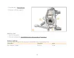
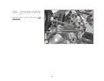
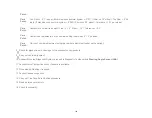
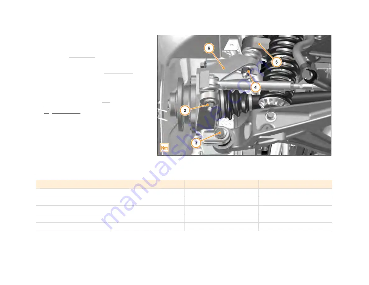
Use a plain M14 half nut and wind
onto the upper and lower ball joint
threads. Torque these nut (4) to
M14 60 Nm . Once torque has
been achieved, remove slave nuts
and fit specified nut (4). Torque
these nut (4) to M14 100 Nm
.
1.
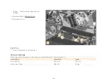
Install components in reverse order.
2.
Check chassis geometry. AA-
RM-03B03-01-002 - Perform a wheel
alignment check
Care
Point:
Once vehicle is on ground.
3.
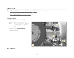
Apply pressure to top of wheel towards
vehicle. If excessive inward movement of
wheel is present, the upper ball joint has
failed. The wishbone will require replacing.
Torque settings
FG03 Chassis / B02 Rear Suspension / Rear Suspension LH / AA-RM-03B02-01-003 - Remove/install upright - Rear
Description
Dimension
Value
Nut Driveshaft
M26
320 Nm
Nut Tie rod - Upright
M12
70 Nm
Bolt Lower wishbone - Upright
M14 x 110
90 Nm
Half Nut wishbone - Upright
M14
60 Nm
Nut wishbone - Upright
M14
100 Nm
136
Summary of Contents for MP4-12C
Page 1: ......
Page 35: ...5 Disc Cross Drilled Hole Chip on disc Do not renew disc 1 34 ...
Page 52: ...2 Detach union nut 2 M10 17 Nm 3 Loosen nut 3 4 Remove front brake hose 4 51 ...
Page 69: ...2 Detach union nut 2 M10 17 Nm 3 Loosen nut 3 4 Remove rear brake hose 4 68 ...
Page 98: ...Description Dimension Value Bolt Floor panel tunnel M6 x 16 10 Nm 97 ...
Page 104: ...1 Remove bolts 1 M6 x 20 4 Nm 2 Remove tyre spoilers 2 Remove front guide vanes 103 ...
Page 105: ...1 Remove screws 1 M6 x 16 6 Nm 2 Remove front guide vanes 2 Remove rear guide vanes 104 ...
Page 125: ...Description Dimension Value Track rod steering rack M14 30 Nm 124 ...
Page 194: ...4 Remove bolts 2 M6 x 20 8 Nm 5 Remove bolts 3 M6 x 16 8 Nm 193 ...
Page 195: ...5 Remove bolts 3 M6 x 16 8 Nm 6 Remove bolts 4 M6 x 16 8 Nm 194 ...
Page 196: ...6 Remove bolts 4 M6 x 16 8 Nm 7 Remove bodyside lower rear arrows 195 ...
Page 203: ...Description Dimension Value Clamp ISG to Throttle M6 5 Nm 202 ...


