Care
Point:
If there is a build up of CCM on the
internal diameter of the disc (1),
this is due to it having a higher
wear rate at the inner part of the
disc (1).
1.
This condition (C) should be matched by the
pad (2). Please note that this does not affect
the performance of the disc (1).
Care
Point:
Discs must be replaced if pad
wear has reached 100%.
If pads have reached 100% wear,
there is a high chance that the
back plate has come into contact
with the braking face (visible mark
will be present).
2.
Discs (1) must be replaced immediately if this
circumstance has occurred due to
contamination of the disc (1).
Care
Point:
Any visual change to the braking
surface of the disc is caused when
the fibres within the CCM
experience a high level of thermal
input. This then causes the fibres
to oxidize, changing the surface
appearance. This condition mainly
occurs after extreme use, such as
racing.
The oxidisation level is calculated
by disc porosity and surface
roughness. Areas that are mainly
affected by the change in the
braking surface are an increase in
pad wear, decreased NVH, and a
decrease in disc performance.
If the level of oxidisation
experienced is very high, the disc
must be replaced. See below for
examples of the different levels of
oxidisation experienced:
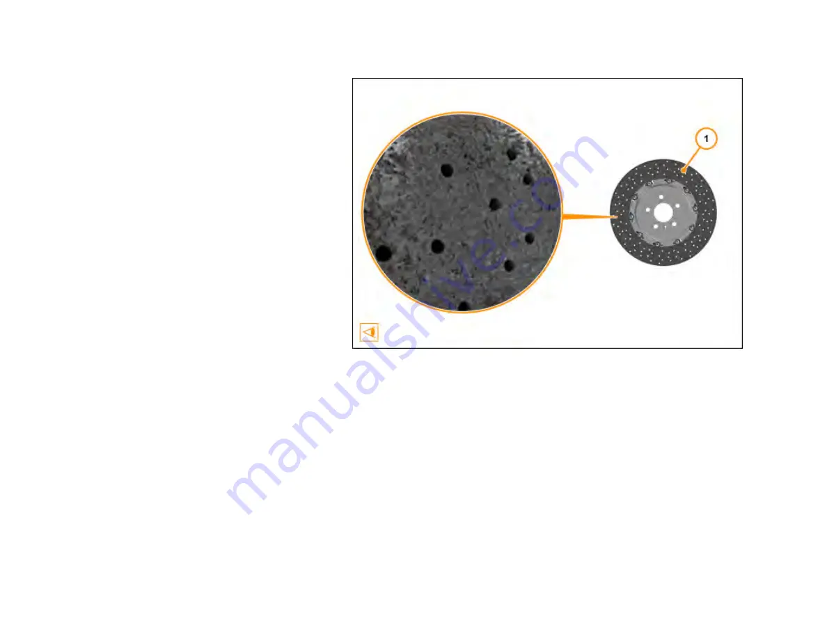
3.
Disc surface (1)
–
Immediately after bedding
–
Do not renew.
4.
Disc surface (1)
–
200 km racing on track
–
Do
not renew.
5.
Disc surface (1)
–
500 km racing on track
–
Do
not renew.
6.
Disc surface (1)
–
1000 km hard racing on
track
–
Check disc weight.
7.
Disc surface (1)
–
1500-2000 km racing on
track
–
Renew disc (end of disc life).
Care
Point:
Tool used when assessing damage must be a precision gauge with a tolerance of 0.1mm.
Care
Point:
If disc is damaged outside of specified figures along the edge of the braking surface, disc must be renewed.
Care
Point:
Any damage on the edge of the braking surface will not affect the disc weight due to the material density.
Checking CCM disc
–
Damage control specifications
29
Summary of Contents for MP4-12C
Page 1: ......
Page 35: ...5 Disc Cross Drilled Hole Chip on disc Do not renew disc 1 34 ...
Page 52: ...2 Detach union nut 2 M10 17 Nm 3 Loosen nut 3 4 Remove front brake hose 4 51 ...
Page 69: ...2 Detach union nut 2 M10 17 Nm 3 Loosen nut 3 4 Remove rear brake hose 4 68 ...
Page 98: ...Description Dimension Value Bolt Floor panel tunnel M6 x 16 10 Nm 97 ...
Page 104: ...1 Remove bolts 1 M6 x 20 4 Nm 2 Remove tyre spoilers 2 Remove front guide vanes 103 ...
Page 105: ...1 Remove screws 1 M6 x 16 6 Nm 2 Remove front guide vanes 2 Remove rear guide vanes 104 ...
Page 125: ...Description Dimension Value Track rod steering rack M14 30 Nm 124 ...
Page 194: ...4 Remove bolts 2 M6 x 20 8 Nm 5 Remove bolts 3 M6 x 16 8 Nm 193 ...
Page 195: ...5 Remove bolts 3 M6 x 16 8 Nm 6 Remove bolts 4 M6 x 16 8 Nm 194 ...
Page 196: ...6 Remove bolts 4 M6 x 16 8 Nm 7 Remove bodyside lower rear arrows 195 ...
Page 203: ...Description Dimension Value Clamp ISG to Throttle M6 5 Nm 202 ...


