19
Connecting to the Junction Box
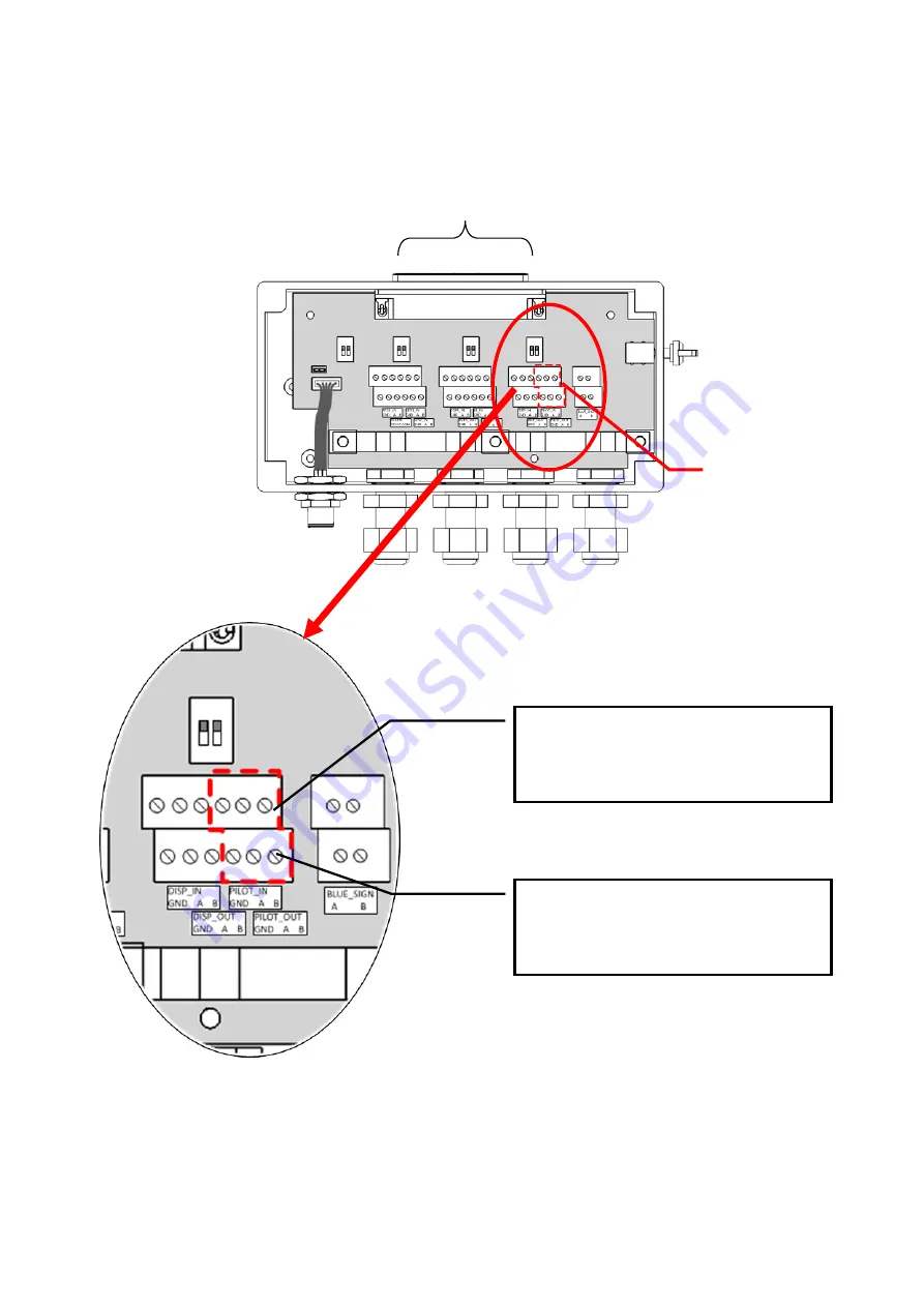
Use the following guidelines to connect the Pilot Plug to the Junction box.
Please refer to section 3.8 External Connectors (Junction Box).
To Transponder Main Unit
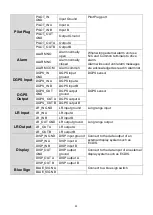
Pilot plug
PILOT_IN A connects to Rx A (Black)
PILOT_IN B connects to Rx B (Green)
PILOT_IN GND connects to Shield
PILOT_OUT A connects to Tx A (Red)
PILOT_OUT B connects to Tx B (White)
PILOT_OUT GND connects to Shield
Note: Shield can connect to either
PILOT_IN GND or PILOT_OUT GND.
Summary of Contents for 21-100-001A
Page 1: ......
Page 2: ...2 ...
Page 3: ...3 Smartfind M5 Class A Inland AIS Installation and Maintenance Manual ...
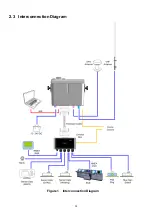
Page 12: ...12 2 3 Interconnection Diagram Figure 1 Interconnection Diagram ...
Page 81: ...81 6 MECHANICAL DIMENSIONS 6 1 Smartfind M5 Transponder Main Unit Front size mm Side size mm ...
Page 82: ...82 Back size mm Bottom size mm ...
Page 83: ...83 6 2 Junction Box 6 3 Extension Cable 6 4 Mounting Template not to scale 85 mm 55 mm 165 mm ...
Page 84: ...84 6 5 GPS Antenna 6 6 Pilot Plug 2 m 60 mm 40 mm 60 mm 80 mm 103 92 mm ...
Page 112: ...112 Note ...
Page 113: ...113 21 135 001N Issue 15 ...
Page 114: ......

