70
4.11.5 Factory
This section is password protected and can only be accessed using the password (see 4.11.6).
Press knob to confirm your choice and the following settings will be restored to their original value:
MOB/Friend ship List, destination list, time zone, language, dimmer, CPA/TCPA and system
password.
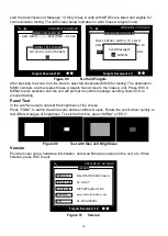
Figure 77
Factory Setting
4.11.6 Password
This submenu enables users to change user password. Certain important information stored within
the transponder can only be changed with the password. Password is required for the access of
the following chapters:
4.8.1 Own Ship
– contains information about call sign, vessel name and ship type
4.8.4 Set MMSI/IMO/ENI
– contains information about MMSI and IMO number
4.11.4 Sensor Configuration
– about baud rate configuration of sensors
4.11.5 Factory
– restoration of factory setting
4.11.10 Alarms Setting
4.11.11 VSWR Setting
(Default password:
“0000”
) This function is for installation only
Use the knob in the order of
“OLD PASSWORD”
,
“NEW PASSWORD”
,
“CONFIRM NEW
PASSWORD”
. Repeat till all four values are entered. To save the settings, press
MENU
or
ESC
and the system will ask whether the changes should be saved. Select
OK
to save or
CANCEL
to
discard and return to main menu.
Figure 78
Password
MENU
MESSAGES
NAV. STATUS
SHIP SETTING
TRANSCEIVER
SYS CONFIG
DIAGNOSTICS
MAIN MENU
2013/01/17 07:18:11
Dangerous Targets :0
Restore factory setting?
OK
CANCEL
WARNING
PASSWORD SETTING
2013/01/17 07:18:11
Dangerous Targets : 0
NEW Password
[ **** ]
Confirm Password [ **** ]
OLD Password
[ **** ]
Summary of Contents for 21-100-001A
Page 1: ......
Page 2: ...2 ...
Page 3: ...3 Smartfind M5 Class A Inland AIS Installation and Maintenance Manual ...
Page 12: ...12 2 3 Interconnection Diagram Figure 1 Interconnection Diagram ...
Page 81: ...81 6 MECHANICAL DIMENSIONS 6 1 Smartfind M5 Transponder Main Unit Front size mm Side size mm ...
Page 82: ...82 Back size mm Bottom size mm ...
Page 83: ...83 6 2 Junction Box 6 3 Extension Cable 6 4 Mounting Template not to scale 85 mm 55 mm 165 mm ...
Page 84: ...84 6 5 GPS Antenna 6 6 Pilot Plug 2 m 60 mm 40 mm 60 mm 80 mm 103 92 mm ...
Page 112: ...112 Note ...
Page 113: ...113 21 135 001N Issue 15 ...
Page 114: ......


