10
1 WHAT IS AIS?
The Automatic Identification System (AIS) is a Very High Frequency (VHF) radio broadcasting
system that transfers packets of data over the VHF data link (VDL) and enables AIS equipped
vessels and shore-based stations to exchange identification information and navigational data.
Ships with AIS transponders continually transmit their ID, position, course, speed and other data to
all nearby ships and shore stations. Such information can aid greatly in situational awareness and
provide a means to assist in collision avoidance.
AIS equipment is standardized by ITU, IEC, IALA and IMO and is subject to approval by a
certification body. The following AIS devices have been developed for variant applications.
AIS Class A:
mandated by the IMO for vessels of 300 gross tonnages and upwards engaged on
international voyages, cargo ships of 500 gross tonnages and upwards, as well as passenger
ships. It transmits typically on 12.5 watt output power.
Inland AIS:
all the features of a Class A transceiver with the addition of features required for Inland
waterways.
AIS Class B:
provides limited functionality and is intended for non-SOLAS commercial vessels and
recreational vessels. It transmits typically on 2 watt output power.
AIS Base Station:
is provided by aids-to-navigation authorities to enable the ship to shore / shore to ship
transmission of information. Networked AIS Base Stations can assist in providing overall
maritime domain awareness.
AIS AtoN (Aids to Navigation):
provides an opportunity to transmit position and status of buoys and lights through the same
VDL, which can then show up on AIS-ready devices within the range.
AIS SART:
Search and Rescue Transmitter using AIS can be used to assist in determining the location of
a vessel in distress. It is typically used on life rafts.
AIS on Search and Rescue (SAR) Aircraft:
used on airplanes and helicopters to assist search and rescue operation.
Summary of Contents for 21-100-001A
Page 1: ......
Page 2: ...2 ...
Page 3: ...3 Smartfind M5 Class A Inland AIS Installation and Maintenance Manual ...
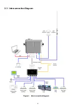
Page 12: ...12 2 3 Interconnection Diagram Figure 1 Interconnection Diagram ...
Page 81: ...81 6 MECHANICAL DIMENSIONS 6 1 Smartfind M5 Transponder Main Unit Front size mm Side size mm ...
Page 82: ...82 Back size mm Bottom size mm ...
Page 83: ...83 6 2 Junction Box 6 3 Extension Cable 6 4 Mounting Template not to scale 85 mm 55 mm 165 mm ...
Page 84: ...84 6 5 GPS Antenna 6 6 Pilot Plug 2 m 60 mm 40 mm 60 mm 80 mm 103 92 mm ...
Page 112: ...112 Note ...
Page 113: ...113 21 135 001N Issue 15 ...
Page 114: ......


