www.mcohome.com User Manual
1
Touch Panel Switch
410 Series
Introduction
Touch Panel Switch is a wall panel built-in with Z-Wave Plus module. With its stylish design and
stable performance, the panel can be used to control house-hold electrical appliances like lamp, motor,
coffee machine, TV set etc. It supports basic command class
,
multi channel command class and multi
channel association command class, also works as a repeater in a Z-Wave network. This product can
be included and operated in any Z-Wave network with other Z-Wave certified devices from any other
manufacturers.
Specifications
Power supply: 85~260VAC, 50/60Hz
Z-Wave frequency: 868.42MHz (EU), 865.2MHz (IN) or other frequency customized
Note: If an inductive load wired, please choose model MH-S411H. (LED load: <10A, inrush
current<165A/ 20ms)
Installation Instructions
IMPORTANT:
A qualified electrician with the understanding of wiring diagrams and knowledge of electrical
safety should complete the installation inside the main circuit box (normally outside your house).
Read all instructions and documentation and save for future reference.
Step1 Preparing
CAUTION:
Cut off power supply at circuit breaker or fuse before installation to avoid fire, shock or
death!
Step2 Installation
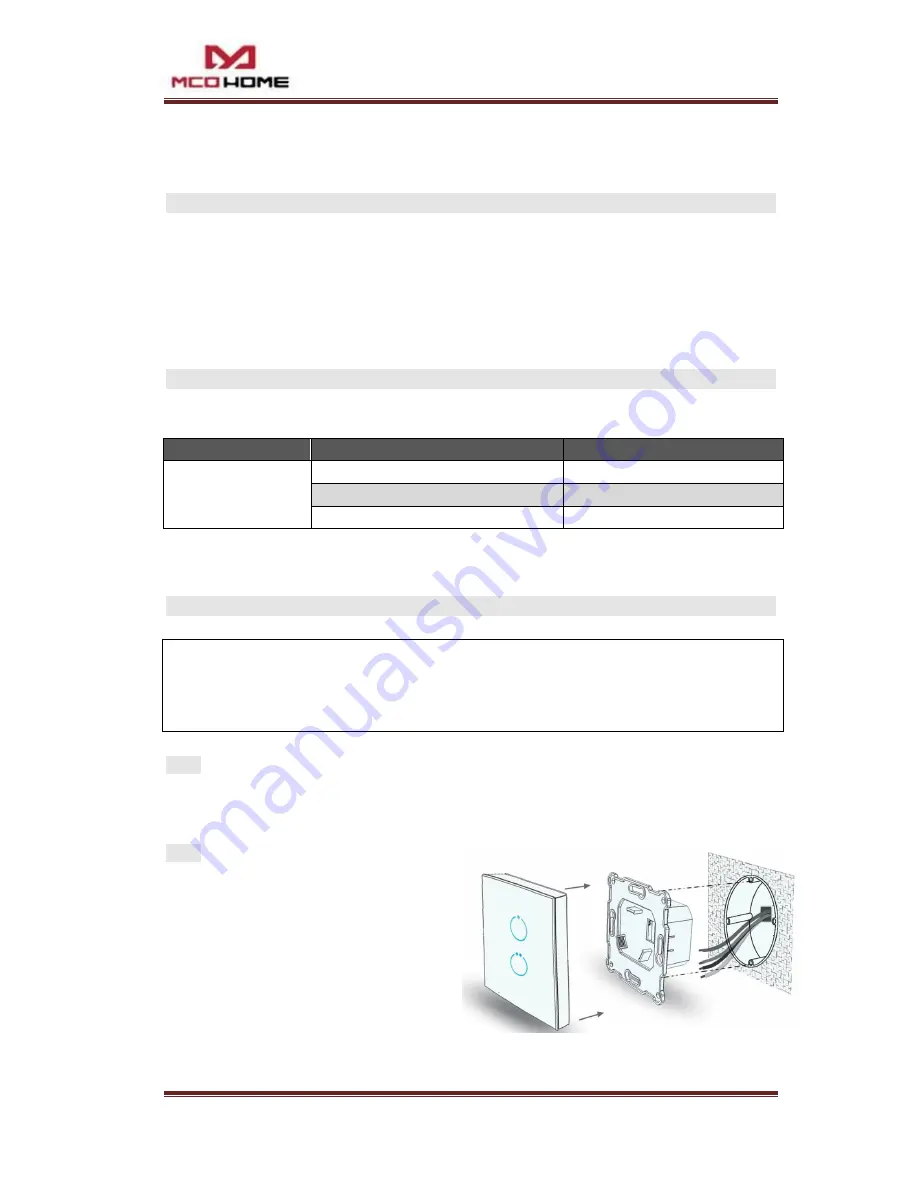
Step 1:
Separate the device into two parts: the
touch panel and the bottom.
Step 2:
Insert all wires into the right terminals by
following the wiring diagrams as below,
and tighten screws.
Step 3:
Secure the bottom part onto a junction box with screws, and then mount the touch panel back.
Step 4:
Confirm the device is well mounted, power on and it is ready to operate.
Item
Models
Max Load
410 series
MH-S411
1*5A
MH-S412
2*5A
MH-S411H
1*10A


