www.mcohome.com User Manual
MCOHome Technology Co., Ltd
3
Note
:
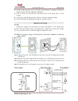
Setback (terminals 3&4)
:
the input terminal controlled by remote; one terminal connect to the
internal power source with a 10K resistor, the other terminal connect to the internal ground
wire.
Relout (terminals 5&6)
:
the output terminal controlled by remote; inside circuit is a OC
output, it can drive a relay that below 24V directly.The maximum drivable current is 30MA.
The internal circuit is shown as above.
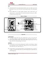
Button & Display
Operation
On/Off operation
ON
:
When it displays OFF, slide up the ON/OFF button to turn it on. Local time, the
corresponding temperature, working mode and output status will be displayed on the screen.
OFF
:
In normal working interface, slide down the ON/OFF button to turn it off. It will
display OFF on the screen and all outputs will be closed.
GFCI Test
Enter into GFCI test
:
In the normal working interface, when the electrical heating is working,
press GFCI button, the icon of GFCI will be displayed on the screen, and the output of
electrical heating is closed, indicator light is on .
Exit from GFCI test: slide the ON/OFF button to turn it off and then turn it on, the device
will back to the normal working interface, the electrical heating begin to output and the icon
of GFCI disappeared.
Comfort Mode
Time Peiod Mode
Energy-saving Mode
Vacation Mode
Floor High Temperature Limit Alarm
Floor Temp Control
Room Temperature Control
Floor High Temperature Limit
S1:Up
S2
:
Down
S4:
Mode Switch Button
S3:
Local Time/ Time
Period Set Button
S5
:
Confirm
Button/Check the Valve
Cumulative Time
ON/OFF
GFCI Test
Red Indicator Light
Keypad Lock
Remote Icon
Week
Icon of each
Time Period
Local Time
GFCI
Electrical Heating
Celsius
Fahrenheit
Temperature
Set Temp
Indoor Temp
Floor Temp
Room Temp Control


