OM AGSB-5
11
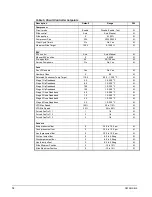
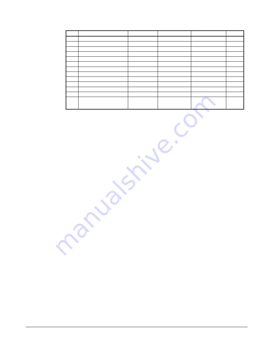
Table 4, Digital Outputs
# Description
Load
Output
OFF Output
ON
Voltage
1
Compressor Starter Contact
Relay
Compressor off
Compressor on
120
2
M1 Contactor (fan 1)
Contactor Coil
Fans off
Fans on
120
3
M2 Contactor (fan 2)
Contactor Coil
Fans off
Fans on
120
4
M3 Contactor (fan 3)
Contactor Coil
Fans off
Fans on
120
5
M4 Contactor (fan 4)
Contactor Coil
Fans off
Fans on
120
6
M5 Contactor (fan 5 & 6)
Contactor Coil
Fans off
Fans on
120
7
Load/Unload Pulse
Solenoid
Hold load slide
Move load slide
24
8 Load/Unload
Select
Relay
Unload
Load
24
9
M7 Contactor (fan 7 & 8)
Contactor Coil
Fans off
Fans on
120
10 Oil
Return
Line
Solenoid
Closed
Open
11 Open
12 Open
13 EXV
Close
Signal
Contact
EXV Follows
0 – 10 VDC
EXV Closed,
Ignores 0 – 10
VDC
10
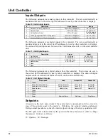
These parameters are digital outputs from this controller. Their values are sent to the correct
pLAN addresses for use by other controllers or displays.
Setpoints
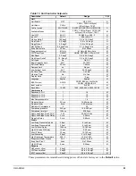
The following parameters are remembered during power off, are factory set to the
Default
value, and can be adjusted to any value in the
Range
column.
The PW (password) column indicates the password that must be active in order to
change the setpoint. Codes are as follows:
O = Operator, password is 100
M = Manager
Entering a Password
The password is located in the unit controller only and can be found at SET, UNIT SPS on
the last menu conveniently located so that you can scroll up one menu to access the
Password Enter Screen.
Summary of Contents for AGS 206A
Page 65: ......


