OM AGSB-5
13
Circuit Operating Mode
The circuits on the chiller can each be individually enable or disabled. Test mode on each
circuit can also be entered independent of the all other circuits. With the circuit switch on,
the circuit mode setpoint offers settings of either Enable or Disable. This simply allows the
circuit to be disabled through a keypad setting.
Cool Mode
When the chiller is in COOL mode, capacity of the compressor is adjusted to maintain
leaving water temperature at the Active LWT setpoint while balancing the load between
running circuits. Load balance offset, LWT error, and LWT slope are used to calculate a
change in slide position.
ICE Mode
Ice mode is designed to have the compressors run at full load until the LWT setpoint is
reached, then shut off until the next ice making cycle starts. ICE settings are made in the
unit controller.
In ICE mode, the compressor capacity is increased at the maximum rate continuously until
reaching the maximum slide position. Load balancing, LWT error, and LWT slope are
ignored. Low and high pressure events are disabled.
An adjustable Start-to-Start Ice Delay Timer will limit the frequency with which the chiller
may start in ICE mode. The timer starts when the first compressor starts while the unit is in
ICE mode. While this timer is active, the chiller cannot restart in ICE mode. The time
delay is user adjustable.
The Ice Delay Timer may be manually cleared to force a restart in ICE mode. A set point
specifically for clearing the ICE mode delay is available. In addition, cycling the power to
the controller will clear the Ice Delay Timer.
Circuit Test Mode
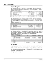
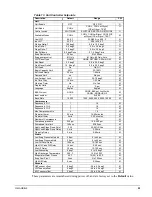
The circuit test mode allows manual testing of all controller outputs. Entering this mode
requires the following conditions.
•
Circuit Switch = OFF
•
Technician password active
•
Circuit Mode setpoint = TEST
A test menu can then be selected to allow activation of the outputs. It is possible to switch
each digital output ON or OFF and set the analog outputs to any value. Upon entering the
test mode, all outputs will always default to the OFF state. Upon leaving the test mode, all
outputs will automatically reset to the OFF state.
Compressors cannot be started in TEST mode.
Slide Position
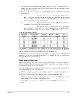
Each compressor will estimate its slide load percentage from the present value of the slide
load indicator. The percentage is based on the 4-20mA signal from the slide load indicator
and varies somewhat by compressor size. A load percentage value of 0 corresponds to mA
Low signal; a percentage value of 100 corresponds to the mA High signal shown in Table 6.
This information is located on the View Cir Status (1) menu. It shows slide position and
slide target.
Table 6, Slide Valve Position
Compressor
Size
mA Low
mA High
205
4.94 14.6
220
4.62 17.0
235
4.32 19.4
NOTE
: See the Physical Data tables in IMM AGSB-60 for unit compressor sizes.
Summary of Contents for AGS 206A
Page 65: ......


