background image

36


OM 

AGSB-5 

A separate alarm log stores the last 25 alarms to occur.  When an alarm occurs, it is put into 
the first slot in the alarm log and all others are moved down one, dropping the last alarm.  In 
the alarm log, the date and time the alarm occurred are stored, as well as a list of other 
parameters.  These parameters include unit state, OAT, LWT, and EWT for all alarms.  If the 
alarm is a circuit alarm, then the circuit state, refrigerant pressures and temperatures, EXV 
control state, EXV position, slide position, and number of fans on are also stored. 
To view alarms, activate the manager password, press Menu on the unit controller, then 
select Alarm (left arrow), then select Active or Log. 

Event Logging 

An event log similar to the alarm log holds the last 25 events to occur.  When an event 
occurs, it is put into the first slot in the event log and all other entries are moved down one, 
dropping the last event.  Each entry in the event log includes an event description, as well as 
the time and date of the occurrence.  No additional parameters are logged for events. 

To view events, press Menu on the unit controller, then select Alarm (left arrow), then scroll 
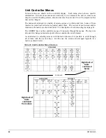
left to Event Log.  See menu matrix on page 40. 

Summary of Contents for AGS 206A

Page 1: ...5 Group Chiller Part Number 331373201 Date June 2005 Supersedes OM AGSB 4 GeneSys Air Cooled Screw Compressor Chiller AGS 230A B through AGS 475A B 60 Hertz AGS 206A B through AGS 411A B 50 Hertz Sof...

Page 2: ...oller Menus 40 Screen Definitions 41 SET Screen Definitions 43 Circuit Controller Menus 47 Screen Definitions 47 SEQUENCE OF OPERATION 52 START UP AND SHUTDOWN 54 Expansion Valve Operation 55 Extended...

Page 3: ...on of the equipment being controlled CAUTION Static sensitive components A static discharge while handling electronic circuit boards can cause damage to the components Discharge any static electrical...

Page 4: ...iagnostics to inform operators of warning and fault conditions in plain language All events alarms and faults are time and date stamped for identification of when the fault condition occurred In addit...

Page 5: ...are labeled CIRCUIT CONROL In addition to providing all normal operating controls the MicroTech II control system monitors equipment protection devices on the unit and will take corrective action if...

Page 6: ...nimum and maximum setpoints These setpoints simply cut off the value to a working range and this range can be limited to a single value if the two setpoints are set to the same value CPU Error These a...

Page 7: ...d Setpoint The psi evaporator pressure setting at which the controller will not allow further compressor loading Low High Superheat Error The difference between actual evaporator superheat and the sup...

Page 8: ...p Stage On or Stage Up is the act of starting a compressor or fan when another is still operating The two phrases are interchangeable and either one can be used depending on the date of issue of the s...

Page 9: ...FT RIGHT have three modes of use 1 Scroll between data screens in the direction indicated by the arrows default mode 2 Select a specific data screen in the menu matrix using dynamic labels on the righ...

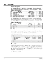
Page 10: ...12 F 7 Slide Load Indicator 4 to 20 mA 0 to 100 8 Open NOTE Value at the converter board input Value at the converter board output is 0 1 VDC 0 9 VDC These parameters are analog inputs to the circuit...

Page 11: ...l Return Line Solenoid Closed Open 11 Open 12 Open 13 EXV Close Signal Contact EXV Follows 0 10 VDC EXV Closed Ignores 0 10 VDC 10 These parameters are digital outputs from this controller Their value...

Page 12: ...0 20 0 o F M Stage 2 Up Deadband 8 0 1 0 20 0 o F M Stage 3 Up Deadband 10 0 1 0 20 0 o F M Stage 4 Up Deadband 12 0 1 0 20 0 o F M Stage 1 Down Deadband 8 0 1 0 20 0 o F M Stage 2 Down Deadband 7 0...

Page 13: ...not restart in ICE mode The time delay is user adjustable The Ice Delay Timer may be manually cleared to force a restart in ICE mode A set point specifically for clearing the ICE mode delay is availab...

Page 14: ...d on the right is for unload oil feed In Circuit Enable mode normal operation the controller makes decisions to move the Slide target the calculated value and pulses the proper solenoid in order to ke...

Page 15: ...ompressor is to start or stop and the scenario for doing so Starting Staging up no compressors on the unit are running The first compressor can start when the LWT is more than the sum of the active LW...

Page 16: ...of Operation The following conditions override the automatic slide control when the chiller is in COOL mode or ICE mode These overrides keep the circuit from entering a condition in which it is not de...

Page 17: ...target will be adjusted down 2 every 5 seconds as long as the superheat remains below 20o F Maximum LWT Pulldown Rate The maximum rate at which the leaving water temperature can drop is limited by the...

Page 18: ...ere the compressor needs to shut down normally a pumpdown will be performed The slide target will automatically go to 0 while pumping down and the compressor will run until the pumpdown pressure has b...

Page 19: ...arget until it is equal to the saturated condenser temperature target setpoint This will allow the VFD to slowly bring the saturated condenser temperature back down Condenser Target This logic is only...

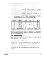
Page 20: ...ambient temperature When the compressor starts a FanTrol stage is forced based on the following table Table 8 Forced Staging Outside Air Temperature FanTrol Stage At Start 75 o F Forced FanTrol 1 SP...

Page 21: ...EXV 100 100 Max EXV 0 Min EXV 0 EXV Control Range 0 Slide Position EXV Steps Min EXV 100 1 Pre Open At the time of a start request the EXV will perform a pre open function This is to provide sufficien...

Page 22: ...pressure unload occurs Starting with F code when suction pressure drops below the low evaporator pressure unload setpoint the controller will switch from subcool control to pressure control until suf...

Page 23: ...peration in an off state see Unit Test Mode on page 28 Evaporator Oil Return Line Control The oil return solenoid shall be on any time the compressor is running and any of the following occurs Slide p...

Page 24: ...Switch 0 VAC Stop 24 VAC On 2 Remote Switch 0 VAC Stop 24 VAC Start 3 Evaporator Water Flow Switch 0 VAC No Flow 24 VAC Flow 4 Mode Switch 0 VAC Cool 24 VAC Ice 5 Open 6 Open The following parameters...

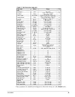
Page 25: ...English M BAS Protocol NONE NONE BACnet LonWorks CAREL MODBUS N2 M Ident number 1 0 200 M Baud Rate 19200 1200 2400 4800 9600 19200 M Compressors Sequence Cir 1 1 1 3 M Sequence Cir 2 1 1 3 M Sequence...

Page 26: ...0 F Fan VFD Y 0 60 F Unit Enable Enabling and disabling the chiller is controlled by the Unit Enable Setpoint with options of OFF and ON The Unit OFF input unit On Off switch field installed Remote st...

Page 27: ...N x ON ON NETWORK x x OFF OFF ON NETWORK OFF x x OFF ON NETWORK ON x ON ON All methods of disabling the chiller except for the unit switch will cause a normal shutdown of any running circuits Any time...

Page 28: ...col COOL w Glycol KEYPAD x ICE w Glycol x COOL ICE w Glycol ICE w Glycol NETWORK x x COOL COOL ICE w Glycol COOL w Glycol NETWORK x x ICE COOL ICE w Glycol ICE w Glycol x x x x ICE w Glycol ICE w Glyc...

Page 29: ...dicator You will see a selection to choose the slide pulse direction with the options of Load left coil or Unload right coil Then there is a selection to turn the pulse on or off Choose on for the Pul...

Page 30: ...point 4 degrees F Leaving Water Temperature LWT Reset The Active Leaving Water setpoint is set to the current Leaving Water Temperature LWT setpoint unless the unit is in COOL mode and any of the rese...

Page 31: ...4 20 mA Input Signal The Active Leaving Water setpoint is adjusted by the 4 to 20 mA reset analog input Parameters used 1 Cool LWT setpoint 2 Max Reset setpoint 3 LWT Reset signal Reset is 0 if the r...

Page 32: ...Reset setpoint 3 OAT Reset is 0 if the outdoor ambient temperature is greater than 75 F From 75 down to 60 F the reset varies linearly from no reset to the max reset at 60 F At ambient temperatures l...

Page 33: ...s below evap freeze protect setpoint Rapid Stop Leaving Evaporator Water Temperature Sensor Fault Sensor shorted or open Rapid Stop Outside Air Temperature Sensor Fault Sensor shorted or open Normal S...

Page 34: ...elf clearing in the starter itself Alarms triggered by these faults will be allowed to self clear twice per day The third will trigger a manual reset in the controller requiring it to be cleared via t...

Page 35: ...minutes Pumpdown and stop Comp state off Oil Level Low DI9 Open for Time greater than Low Oil Level Delay AND more than one hour since last occurrence Rapid stop Comp state off Failed Pumpdown Circui...

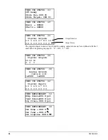
Page 36: ...lide position and number of fans on are also stored To view alarms activate the manager password press Menu on the unit controller then select Alarm left arrow then select Active or Log Event Logging...

Page 37: ...key 3 Change field values in edit mode according to the following table LEFT Default D RIGHT Cancel C UP Increment DOWN Decrement These four edit functions are indicated by one character abbreviation...

Page 38: ...efault changes a value to the factory set default value RIGHT key Cancel cancels any change made to a value and returns to the original setting UP key Increment increases the value of the setting DOWN...

Page 39: ...anager If the wrong password is entered a temporary message will appear so stating If no valid password is active the active password level displays none Entering an incorrect password while a passwor...

Page 40: ...croll through all of them with the 4 arrow keys For this use the screens are arranged logically in a matrix as shown below Table 25 Unit Controller Menu Structure VIEW MENUS VIEW UNIT STATUS 1 VIEW UN...

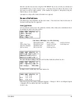
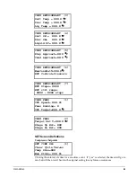
Page 41: ...gs are entered to these screens VIEW UNIT STATUS 1 Unit Status Unit Mode Evap Pump run Unit Status will display one of the following Auto Off Keypad Disable Off Test Mode Auto Wait for flow Off Ice Mo...

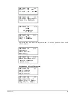
Page 42: ...IEW CIR N STATUS 1 Off Ready Slide Position 000 0 Slide Target 000 0 Slide position and slide target are explained on page 18 VIEW CIR N STATUS 2 Hours XXXXX Starts XXXXX VIEW REFR CIR N 1 Evap Press...

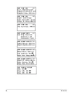
Page 43: ...rm or event could be shown The alarm log and event log can show up to the 25 most recent occurrences EVENT LOG 1 25 Event Description hh mm mm dd yy ALARM LOG 1 25 Alarm Description hh mm ss dd mmm yy...

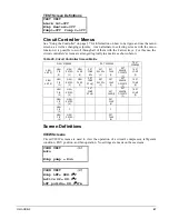
Page 44: ...able effect of increasing compressor cycling The StopDelta is the number of degrees below the chilled water setpoint the water temperature must fall for the last compressor to stop The StageDelta is t...

Page 45: ...its F psi Lang ENGLISH Inch Pound units of measure and English language are the only options available in this software version SET UNIT SPs 12 Protocol Ident Number Baud Rate SET UNIT SPs 13 Enter Pa...

Page 46: ...SPs 5 Stg Up Delay XXXsec SET ALARM LMTS 1 Low Evap Pressure Hold 59 0 psi Unload 58 0 psi SET ALARM LIMITS 2 LowOilDelay XXX sec HighOilDpDel XXX sec SET ALARM LIMITS 3 MinLiftDel XXX sec Low Subcool...

Page 47: ...SET SCREENS TEST SCREENS VIEW UNIT 1 VIEW CIR 1 VIEW REFRG 1 VIEW FANS 1 SET COMP SPs SET EXV SPs 1 SET FANS 1 SET SENSOR OFFSETS 1 TEST COMP 1 VIEW UNIT 2 VIEW CIR 2 VIEW REFRG 2 VIEW FANS 2 SET COMP...

Page 48: ...outputs in menu 5 are defined in Table 2 and Table 4 beginning on page 10 0 Off 1 ON VIEW CIR STATUS 4 Digital Outputs 11 12 13 0 0 0 VIEW CIR STATUS 5 Analog Outputs volts X 100 1 XXXX 3 XXXX VIEW C...

Page 49: ...VIEW REFRIGERANT 7 EXV Steps XXXX EXV ctrl range XXXX XXXX steps VIEW FANS 1 VFD Speed XXX X Fans Running X VFD Target XXX X F VIEW FANS 2 Target Sat T XXX X F Stage Up Err XXX Stage Dn Err XXX SET Sc...

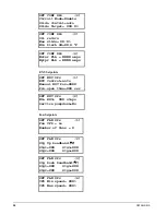
Page 50: ...NNNN amps EXV Setpoints SET EXV SPs 1 EXV Control auto Manual EXV Pos XXXX Pre open time XXX sec SET EXV SPs 2 Min EXV XXX steps Service pumpdown No Fan Setpoints SET FAN SPs 1 Fan VFD no Number of f...

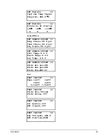
Page 51: ...Press XX X psi Liq Press XX X psi SET SENSOR OFFSET 2 Suct Temp X X F Disch Temp X X F Liq Temp X X F SET SENSOR OFFSET 3 Slide min pos XX Slide max pos XX Slide Pos XXX X Test TEST CIRCUIT 1 Fans 1 O...

Page 52: ...cating panel such a BAS protocol interface The display will show OFF RemoteComm if this operating mode is in effect If an alarm condition exists which prevents normal operation of both refrigerant cir...

Page 53: ...activate the remaining condenser fans as needed to maintain proper condenser pressure The MicroTech II controller continuously monitors the condenser minus evaporator lift pressure and will adjust th...

Page 54: ...cy must perform initial start up in order to activate warranty CAUTION Most relays and terminals in the unit control center are powered when S1 is closed and the control circuit disconnect is on There...

Page 55: ...ressure target The base pressure target is calculated using the following formula Base target 2 3LWT 8 The base target is limited to a range from the low pressure inhibit set point plus 2 psi up to 52...

Page 56: ...ompressors have pumped down turn off the chilled water pump CAUTION Do not turn the unit off using the S1 switch without first moving PS1 and PS2 to the Stop position unless it is an emergency as this...

Page 57: ...glycol is not used in the system drain all water from the unit evaporator and chilled water piping if the unit is to be shutdown during winter Do not leave the vessels or piping open to the atmosphere...

Page 58: ...rcuit The control power can be rewired to a separate 115V supply do not wire directly to the heater If this is done the disconnect switch should be clearly marked to avoid accidental deactivation of t...

Page 59: ...ese figures are examples only and cannot be appropriate to every situation Generally for an extended margin of protection select a temperature at least 10 F lower than the expected lowest ambient temp...

Page 60: ...DSH drops below 20 then it will unload Excessive refrigerant charge excessive oil a large amount of oil in circulation and a leaking or over feeding evaporator solenoid valve will all cause low discha...

Page 61: ...tween 20 and 22 DSH the compressor will not load up and will be in an low discharge superheat inhibit event The higher the refrigerant flow the more liquid carry over we will get from the flooded evap...

Page 62: ...rry over will result in higher discharge superheats More liquid carry over will occur when 1 The refrigerant circuit is overcharged 2 Excessive oil is in the evaporator 3 Mass flow rate of compressor...

Page 63: ...ACnet When selected the ident number and baud rate setpoints are not available Baud rate is locked at 19200 The factory installed kits on the MicroTech II controller are as follows BACnet Kit P N 3501...

Page 64: ...MAX N 120 VAC 85 2 CHW PUMP RELAY 2 BY OTHERS 120 VAC 1 0 AMP MAX N 120 VAC 81 75 24 VAC ALARM BELL RELAY FACTORY SUPPLIED ALARM FIELD WIRED ALARM BELL OPTION TB1 24 VAC OR 30 VDC 71 72 69 60 67 NOR...

Page 65: ......
Page 66: ...y International 800 432 1342 www mcquay com OM AGSB 5 6 05 This document contains the most current product information as of this printing For the most up to date product information please go to www...

Reviews: