40
OM
AGSB-5
Unit Controller Menus
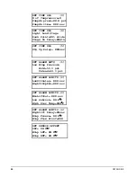
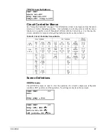
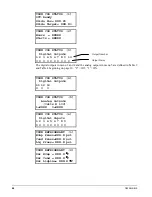
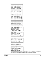
Various menus are shown in the controller display. Each menu screen shows specific
information. In some cases menus are used only to
view
status of the unit, in some cases
they are used for checking
alarms
, and in some case they are used to
set
the setpoint values
that can be changed.
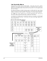
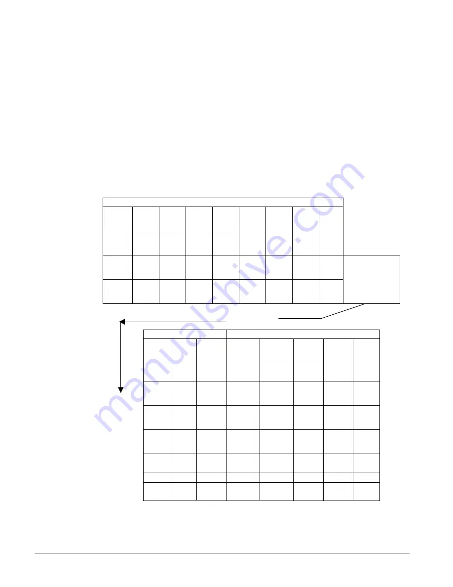
The menus are arranged in a matrix of screens across a top horizontal row. Some of these
top-level screens have sub-screens located under them. The content of each screen and its
location in the matrix are shown in Table 25. A description of each menu begins on page 41.
The ARROW keys on the controller are used to navigate through the menus. The keys are
also used to change numerical setpoint values contained in certain menus.
As an alternate to selecting screens with the menu function, it is possible to scroll through
all of them with the 4 arrow keys. For this use, the screens are arranged logically in a
matrix as shown below.
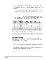
Table 25, Unit Controller Menu Structure
VIEW MENUS
VIEW
UNIT
STATUS
(1)
VIEW
UNIT
TEMP
(2)
VIEW
CIR #1
(1)
VIEW
CIR #2
(1)
VIEW
CIR #3
(1)
VIEW
REFRG
CIR #1
(1)
VIEW
REFRG
CIR #2
(1)
VIEW
REFRG
CIR #3
(1)
VIEW
FANS
On-Off
(1)
VIEW
UNIT
STATUS
(2)
VIEW
UNIT
TEMP
(2)
VIEW
CIR #1
(2)
VIEW
CIR #2
(2)
VIEW
CIR #3
(2)
VIEW
REFRG
CIR #1
(2)
VIEW
REFRG
CIR #2
(2)
VIEW
REFRG
CIR #3
(2)
VIEW
FANS
VFD
(2)
VIEW
UNIT
STATUS
(3)
VIEW
UNIT
STATUS
(4)
VIEW
REFRG
CIR #1
(5)
VIEW
REFRG
CIR #2
(5)
VIEW
REFRG
CIR #3
(5)
Right half of
table
continued
below
ALARM MENUS
SET MENUS
EVENT
LOG
(1)
ALARM
LOG
(1)
ALARM
ACTIVE
(1)
SET UNIT
SPs (1)
SET
COMP SP
(1)
SET
ALARM
LMTS (1)
SET
SENSOR
OFFSET
TEST
UNIT
SET UNIT
SPs
(2)
SET
COMP SP
(2)
SET
ALARM
LMTS
(2)
EVENT
LOG
(25)
ALARM
LOG
(25)
ALARM
ACTIVE
(n)
SET UNIT
SPs
(3)
SET
COMP SP
(3)
SET
ALARM
LMTS
(3)
SET UNIT
SPs
(4)
SET
ALARM
LMTS
(4)
Right half of
table
continued
from above
SET UNIT
SPs
(5)
SET
ALARM
LMTS
(5)
SET UNIT
SPs
(6)
SET UNIT
SPs
(to 13)
Continued
Summary of Contents for AGS 206A
Page 65: ......


